AM4384: RTC crystal load capacitance
UCD90160A: UCD90160A - Current monitoring
Part Number:UCD90160A
It could be beneficial for my design to sequence and monitor more than 12 power rails (mixed current and voltage monitoring). The UCD90160A device seems like a right part for the job but in its datasheet there is no mention about current monitoring. In contrast, UCD90120A has a separate section for current monitoring.
Is the UCD90160A device suitable for current monitoring when using with a current shunt monitor (ie.INA196)?
Linux/AM5728: ARM and DSP shared memory
Part Number:AM5728
Tool/software: Linux
I am trying to combine the ALSA API and the OpenCL API to realize an audio real-time application.
I would like to use the OpenCL's MapBuffer() function to map the CPU's application buffer to the kernel's argument.
The function based on the DSP and CPU is using the same SDRAM. I don't know where can I know this information
Is it possible?
TPL5010: Replacement parts for TPL5010
Part Number:TPL5010
Hi,
We are using the TPL5010 as a WDT in our system, but the last few board spins we've done we've encountered issues with sourcing parts. Is this going EOL or being replaced by another part soon? I see there is the -Q1 version of this IC, but it's a little more expensive.
Are there alternatives from TI we should look into?
Thanks,
Eric Myers
LMK03318: programming issue
Part Number:LMK03318
Team,
We are suffering the programming issue on MTK platform which we WIN on reference design and then extend to my customer’s project for China end customer.
Let me try to step-by-step list what we did and result.
Customer bought LMK03318 as catalog part without MTK’s code because of easy management.
Therefore, they are trying to program LMK03318 on system board by CPU through I2C interface.
How they got the setting: Open Code Loader à click “File” à click “Restore” à choose the attached file à go to “Register” page à export register value in hex to text file
Therefore, we copy all of register value and then past into the excel file of “LMK03328 EEPROM programming…….”
Then, SW team followed the instruction on excel to get “non #” register value and then write into their host.
Then, SW team followed the programming instruction on datasheet to write setting into LMK03318.
Finally, it is unsuccessful to store the code into LMK03318 and also change the address from 0x53 to 0x03. We try to GUI to re-write again with 0x03 address and then power recycle. The address will go back to 0x53.
We suspected of their i2c format or timing wrong to cause this weird behavior. So, we tried to simplify as just write a signal register bit to shut down one of channel. I did that on EVM board and then measuring CLK and DATA waveform to compare the waveform their host did.
we tried to shut down CH7 by setting R30 bit[5]=1. The waveform is the same with what we measure on EVM board. we still didn’t find the root cause why their host write the code into lmk03318 will fail even changing the i2c address.
Due to time is too tight, customer is eager to do the small production in factory (it is in China). So, we tried to give up the way above and then choosing to use GUI to program lmk04906 at this moment. Therefore, we send the download like for cold loader and instruction on how to import the setting file as attached and then programming lmk03318 through GUI.
Now, their China team feedback that after programing and power recycle, the i2c address will become from 0x53 to 0x03. You can see it on customer screen shot below. in my customer, they also feedback they also suffer this issue on their side.
Again, I suspected of something wrong on system board. there may be something else to affect it to cause changing address. so, we brought LMK03318 in my customer to test it again with their laptop. We can’t believable te issue can be duplicated on EVM board. we just use GUI and then restore the setting which is generated from product line team. We tried to use my laptop to do the same thing. The issue is disappear. It looks like that not every laptop can program lmk03318 with GUI successfully. We use the same .mac file as well as the same version code loader and windows version.
Please help to quickly help to find the root cause to solve this issue ASAP. Customer is going to rise the complain about bad experience and they are asking us to standby in their production line to manually program lmk03318 at this small production by using my laptop.
DRV8323: DRV8323
Part Number:DRV8323
Hallo,
It concerns the CAL input of the DRV8323.
I designed the layout so that I can apply the DRV8323RH or the DRV8323RS
It is ferry difficult to add to the CAL signal in the design, also I do not yet understand how the CAL signal works.
The question is : can you advice my about CAL signal for the DR8323RH and the DRV8323RS.
Thanks in advance.
L.v. Rijn
TL494: TL494- DC-DC converter -metal core constant current 200W module
Part Number:TL494
Hi
I am using a typical Chinese DC-DC converter (constant current) 250W assembled on a metal core laminate to drive some string leds.
The configuration is : input : 12 VDC - 2,5A - Output 25V- 1,2A - total 30W. I firstly used 10 samples to submit 2 month test and they worked well.
Now I have a customer order of 1000 pcs and ordered the dc-dc converters direct from china. The module is based on TL 494 with 2 tripots for output current and voltage adjust.
When I started testing the product, I noticed all the batch is producing a peak of current when I turn on the PS. Such peak of current , when adjusted for 12V input, occurs for around 0,5 seconds during startupand the system returns to the voltage and current previously adjusted. If i reduce the input voltage to less than 11VDC, the peak occurs but the system does not return to adjusted values, As result, the pcb increses the temperature and will fattaly burn the module.
I replaced the TL 494 bey new ones and notices the modules became muc,much more stable, but I still notice a little peak of current in voltages lower than 12V. In this case , it is only a start up peak and the circuit starts working. I claerly noticed there is something wrong with the original TL494 that came with the batch. Has anyone experienced such problem already? Is it the TL494 the responsible for such peak , or could be a deffective capacitor of the typical application?
CC1100: Assistance with selection of a 868MHz RF module
Part Number:CC1100
Hello,
I would need assistance with selection of a RF module for IoT sensor project.
Requirements:
- Very low power (With timer on and during send/receive)
- As long transmission distance as possible
- 868MHz with integrated stack (ZigBee or other) or in other way suitable for rapid development against an gateway system of choice.
- Mesh features are not required.
Best Regards
TUSB8043: Programming external EEPROM
Part Number:TUSB8043
Hello,
we made a design with the TUSB8043, it works perfect. But we have in one downstream a layout-mistake (switched Dp/Dn). I've seen in the datasheet that this two signals can be switched with a bit in the registers. We have the fallback-EEPROM in the layout provided.
Now i'm looking for a tool to program this chip through the HID-to-I2C bridge. Alternatively a default datadump of the eeprom would be very helpful. In that case, i can change the concerning bit and program the chip externally.
Where can i download this tool?
Thanks in advance
Declaration files
Hi, I was using CCS v7 for MSP430.....I was getting the following errors:
#225-D function "send_cmd","delayms", "LCD_Init","send_string" declared implicitly......for this i have refered "processors.wiki.ti.com/.../225"......but i didn't get the prototype .h file or a declaration files to add before these........kindly help me in giving these declaration files
Thanks in advance,
likhil
RF430FRL153H: Security feature.
Part Number:RF430FRL153H
Hi Ralph: My customer is wondering do we have any information on what security is available for the RF430FRL153HCRGER chip?
Looking at locking the memory but is there any option that allows the developer only to write to chip?
They wanted this feature so their product could not be altered once on the market.
LM5022: Oscillation concern/question on SW node
Part Number:LM5022
My customer has a Flyback design based on the LM5022 and is concerned about the oscillation he sees on the SW node after the controller turns off the primary side power FET:
This is an isolated supply.
I’m seeing some oscillation on the switching node on both the primary and secondary side of the transformer.
I’ve attached a .pdf of the power supply schematic.
I’ve also attached a .pdf of the schematic, annotated with scope shots of the relevant signals.
All of the probed signals look fine, except the switching nodes.
The oscillation occurs when I raise the input voltage to 48V DC. As I ramp the input voltage down from 48V to 20V, the oscillation gets smaller, and eventually goes away.
Is there a way for me to get rid of the oscillation?
I don't believe this is an issue and have pointed my customer to the PMP7338 reference design 'Test Report' to show that the 'oscillation' is normal. (SNVU139)
Though the PMP20468, PMP20127 and PMP20676 would be better examples, as they are true Flyback designs, while the PMP7338 is a SEPIC.
Feedback on the attached schematics and scope shots would be great. Any App Notes / Articles that explain the LM5022 Flyback operation would also be great and would be of help to me as well!
Thanks!
(Please visit the site to view this file)
(Please visit the site to view this file)
WEBENCH® Tools/LM25011: Webench does not allow Iout minimum to be specified
Part Number:LM25011
Tool/software: WEBENCH® Design Tools
I used Webench to design a 14-18V to 12 V switcher at .350 ma output. It is an incredible tool. I have a DC motor load that is on for only 20 seconds at a time.
1) How does the regulator behave with a dynamic load? I know this is complicated, but any way to estimate if damage can be done to the regulator and overshoot in response?
2) If a minimum load is needed, doesn't seem I can specify thru Webench, though other forms on the TI site allow minimum current to be specified for regulator designs.
Thanks,
Robert
LM5160A: LM5160A/LM5160 Transformer design
Part Number:LM5160A
Dear TI
I consider a LM5160 for FET/IGBT/Sensing Bias Power. I find many application(without transformer design)
Could you recommend the application that contains the transformer design?
or does LM5160 use non_gapped_transformers(Example Full Bridge transformer, very high Lm) instead of gapped_transformers(Example Flyback Transfer , user_defined Lm)?
Best Regards.
CC2640R2F: Does TI have multiple fabs making this part?
Part Number:CC2640R2F
I am considering BLE SoCs for a customer and they are extremely concerned about components being single source having had natural disasters shutdown the single fab making a part they needed in the past. Is there any where I can get information to give my customer showing that TI has multiple fabs making this part?
Thanks
Ben
INA828: Offset Voltage and Operating Temperature
Part Number:INA828
Hi,
1. In page-5 of datasheet VOSI is specified for a Gain=100. Can you please tell me this specification at Gain=1? I would like to get typical, Max values at 25C and max value over the operating temperature of the IC.
2. As per datasheet the operating temperature is -50C to 150C even though the IC is specified from -40C to 125C. Is there any plan to uprate this part to operate from -55C to 125C (or 150C)?
My products operating temperature requirement is from -55C to 125C.
Thanks
Shihab
TIDA-00792: Multiple boards
Part Number:TIDA-00792
Hi,
It is possible to connect more boards in series with the same IC that are already included on the board or it is necessary to implement another MCU to control these two boards.
Thank you
TPS54335A: tps54335a belt can't afford to load
Part Number:TPS54335A
sir:
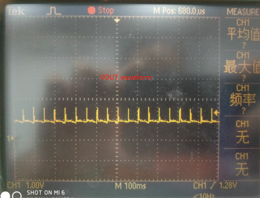
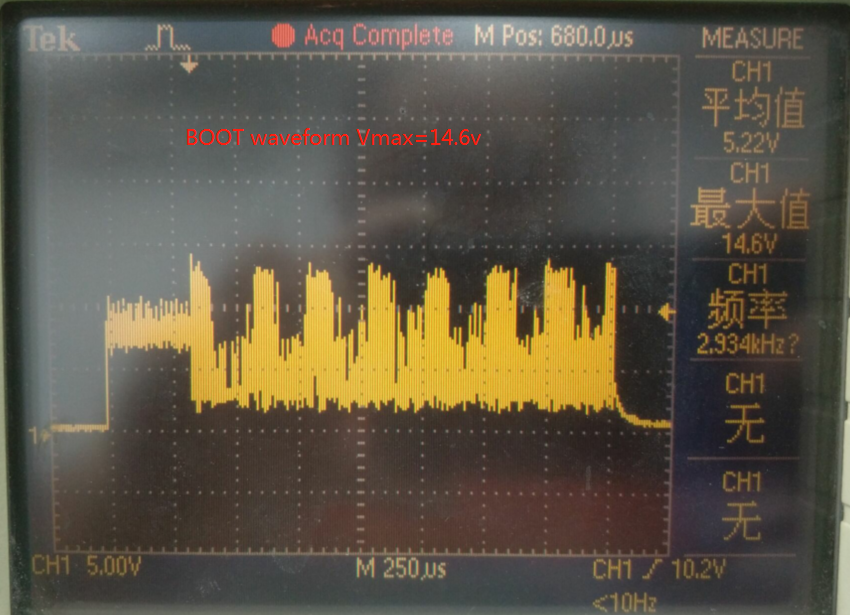
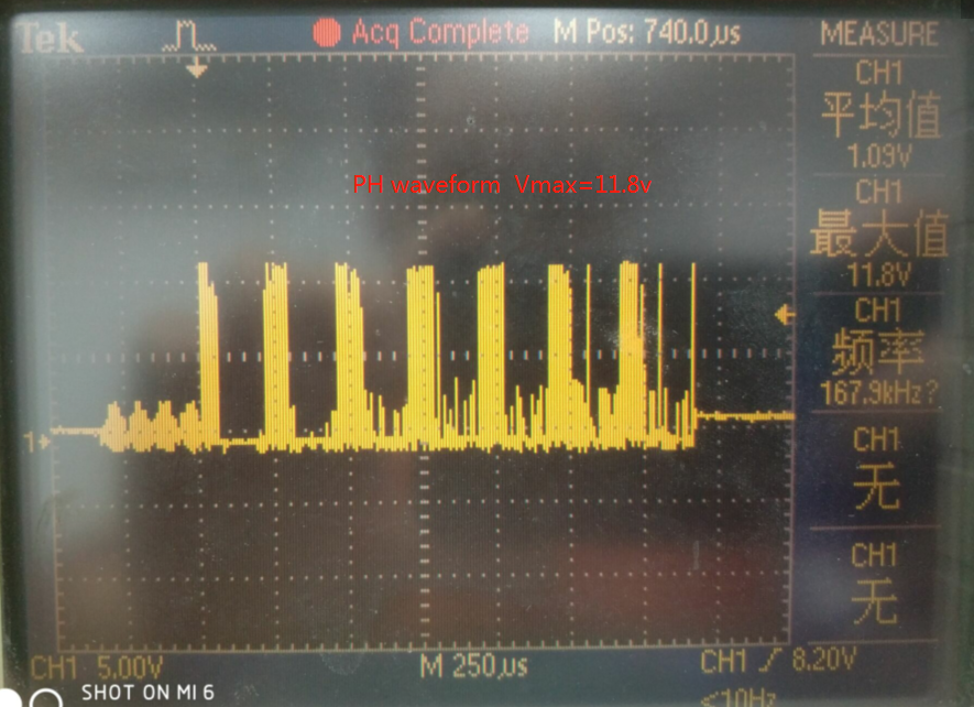
I use WEBENCH circuit design . VIN=12V VOUT=5 IOUT=3A. But in fact, tps54335a belt can't afford to load. the PH, BOOT,VOUT waveform as follow . Q1:What causes it Q2: the bootstrap capacitor value must 0.1 μF ? if change it,what will happen. (my English is not very good) Thank you for your support.
BQ25606: Blinking status LED
Part Number:BQ25606
Hi everyone,
I'm cureently designing a Board for charging a 18650 1S2P Battery of 5200mAh to 1 A rate, actually I power my board with a laboratory Power supply but in customer condition it will be with a 5V 2,5A .
When I Power my system (a TPS61089RNRR and the main board, for arround 3,5W of consumption) the status Led switch down and if i rise VBUS it start blinking (really faster than 1Hz) untill i rise VBUS arround 9V then status led stay ON.
I've shorted D+ D- cause in this case it will not be used in USB application.
I Have solved this situation by setting my Ichg to 500mA but if i start to use the function of my board (like bluetooth comunication) the charger stop (status of) and never restart (after stopping the BT communication)
Do you have some suggestion?
Thanks in advance
DS80PCI800: PCIe GEN3 redriver/retimer suggestion
Part Number:DS80PCI800
Hello Sirs,
We have a case need PCIe GEN3 redriver/retimer for long distance as attach picture.
Would you pls give me a comment could ds80pci8xx or SN75LVPE802 ok for this case ?
Many thanks !


