↧
TPS7A85: Thermal resistance value
↧
TAS3251: TAS3251 I2S Input (As Slave) Not Working
Part Number:TAS3251
Hi,
My TAS3251EVM is not working. The configuration I set for the TAS3251EVM is as below:
- TAS3251EVM as slave device (I2S)
- The I2S master is from my ADAU1701 (Master) - providing the MCLK, BCLK, SDIN and LRCK to the TAS3251EVM
- J37 - OUT (AIB I2S)
- J30 - SDOUT

And my Purepath3 config is as shown in the image below:

I manage to play the sound from the Checking and the USB (playing a mp3), but cannot get the I2S to work. Please advice. Thanks in advance!
↧
↧
CCS/AM3358: During debugging, need to single step several times before running
Part Number:AM3358
Tool/software: Code Composer Studio
When I start a debug session, I find that I have to manually single-step over the first few instructions before I can press F8 (Resume), otherwise an exception occurs.
Scenario 1:
CCS loads my software onto the target and halts at the first instruction in init.asm. If I then press the Resume button (F8), I get an exception.
However, if I single step a few times (past the assembler code to set up the stacks, over the BSS loop and step into my C entry point and over the first few C instructions), then I can press F8 and everything is fine for the rest of the debug session.
Scenario 2:
I change the gel file to halt at the first C function (it's called start_boot but it's similar to main()), again I need to single step over a few C statements before I can press F8, otherwise I get an exception.
Scenario 3:
I change the gel file to halt at a function some way further on in the code. It never halts there - I'm guessing the exception occurs first.
In all cases, if I gently single-step through the first few instructions, everything is fine. The code also works perfectly when running in a production setting, i.e. booting from ROM without any debugger interactions.
I'm suspecting interactions between the debug settings for the IcePick and A8 - I've found in the past that I need to set "Rest the target on a connect" for the IcePick to make debugging work reliably, but I can't set this for the A8 because I'm relying on my bootloader to initialise peripherals. When the exception occurs, I can see that the CP15 instruction fault status register is 5 (translation fault, section) but the data and instruction fault addresses are both zero.
Is this something that's been seen before? Are there any critical debug settings I need to know about?
↧
TMS320F28069F: Is it OK to set USER_MAX_VS_MAG_PU value bigger than 0.6666 ?
Part Number:TMS320F28069F
Dear TI members,
I have a question about USER_MAX_VS_MAG_PU value.
This value seems to be limited by 0.6666
What is the expected problem if it is bigger than 0.6666, for example 0.8 or bigger ?
Thanks in advance.
Best Regards,
Hae Ryong
↧
Linux/DRA71: viddec3test vDRM error
Part Number:DRA71
Tool/software: Linux
Now I am run the vsdk and IPUMM in IPU2.(VSDK0304) and use vDRM to display.
1. run weston: viddec3test ok.
2. modify the code and run (stop weston) error.
log
root@dra7xx-evm:/# ./viddec3test -s 24:720x420 /usr/share/ti/video/TearOfSteel-Short-720x420.264 --fps 20
0x3cf10: Opening Display..
Forcing playback rate at 20 fps.
using 1 connectors, 1920x720 display, multiplanar: 1
0x3cf10: Opening Demuxer..
Input #0, h264, from '/usr/share/ti/video/TearOfSteel-Short-720x420.264':
Duration: N/A, bitrate: N/A
Stream #0:0: Video: h264 (High), yuv420p, 720x420 [SAR 1:1 DAR 12:7], 24.08 fps, 24 tbr, 1200k tbn, 48 tbc
0x3cf10: infile=/usr/share/ti/video/TearOfSteel-Short-720x420.264, width=720, height=420
0x3cf10: padded_width=896, padded_height=528, num_buffers=19
ERROR:alloc_buffer:184: drmModeAddFB2 failed: Invalid argument (-22)
ERROR:alloc_buffers:228: allocation failed
Segmentation fault (core dumped)
code diff
if (!global_fd) {
//for vdrm
#if 1
global_fd = open("/dev/dri/card1", O_RDWR);
#else
global_fd = drmOpen("omapdrm", NULL);
#endif
if (global_fd < 0) {
ERROR("could not open drm device: %s (%d)", strerror(errno), errno);
goto fail;
}
}
Best Regards,
Fredy
↧
↧
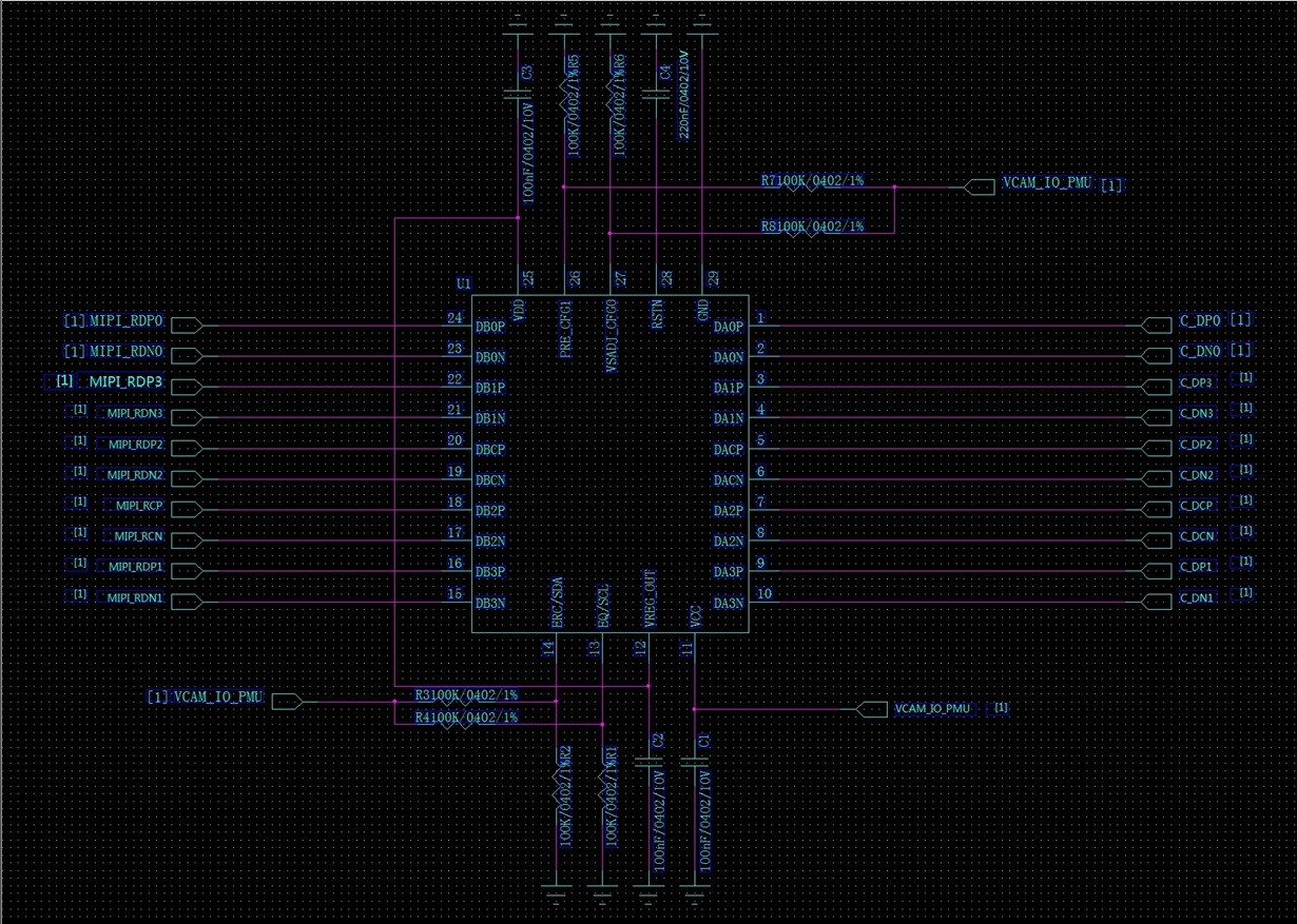
SN75DPHY440SS: confirm circuit schematic
↧
Linux/TMP422: Linux driver temperature calculation
Part Number:TMP422
Tool/software: Linux
Hello team,
I have a question about TMP422 linux driver provided on TI web(http://www.ti.com/tool/TMP421SW-LINUX).
When we obtain temperature range through the driver, we got strange temperature information.
Looking at the source code, I found calculation such as (temp * 1000 + 128) / 256 is run in the driver when returning the temperature data.
1) Could you please let me know a reason of the calculation?
2) What is best way to calculate actual temerature in degree C from the output data?
Best regards,
↧
WL1807MOD: WL1807MOD - High throughput test report
Part Number:WL1807MOD
Hello, team!
My customer has interested WL1807MOD wifi module and he needs following information.
The one of the features of wifi is high throughput: 80 Mbps (TCP) and 100 Mbps (UDP) for 20- and 40-MHz SISO, and 20-MHz 2x2 MIMO at 2.4-GHz
The customer has doubts about the declared characteristics.
Could you please provide test report?
Thanks in advance.
↧
TPS25927: Dual rail protection
Part Number:TPS25927
Hi,
I have a circuit which, in case of failure or overcurrent, needs both Vcc and GND to be disconnected at the same time. I've been looking around and haven't found anything similar. The possible solution I thought of is an e-fuse with an external fet to disconnect the ground, like the one below.

Would this work?
Thanks,
Federico
↧
↧
BQ34Z100EVM: bq34z100 with NiMH
Part Number:BQ34Z100EVM
Hello everyone,
I want to use the bq34z100 for a NiMH pack in 3S1P. The capacity is 4500mAh.
I tried to describe the data memeory with the right values, which I did not succeed. Then I read here soms comments and I tried to write new values in the memory. Unfortunately, I noticed that the bq34z100 no longer assumes new values. The chip is not locked. What am I doing wrong? Should I solder on a new device?
regards
Karl
↧
SN74LV8154: SN74LV8154
Part Number:SN74LV8154
Hi, I have to use the SN74LV8154 in order to be able to count unitl 143sec, there is a minimum frequency clock for the SN74LV8154? and for the Counter in general?
thank you
Regards
Irene Caponigri
↧
RTOS/TDA2PXEVM: ISS ISP SIMCOP Usecase change display background color
Part Number:TDA2PXEVM
Tool/software: TI-RTOS
Hey I am running the standard ISS-ISP-SIMCOP-DISPLAY usecase on the tda2px with psdk3_03. I implemented my sensor and everything works.
Thing is my display capture format is 1104x620, so the output on the display does not exactly fit the actual resolution of the display.
Green bars are left and right of the capture image, probably generated somewhere in the display link or issM2mIsp.
Where can I change those bars to be black instead of green?
best regards,
Nicolas Rausch
↧
UCD3138: Fastest regulation possible
Part Number:UCD3138
Hi,
I am looking for a high-bandwidth DC-DC step down converter solution. For this, switching frequencies in the multi-MHz range are necessary. The intended input voltage is 32V to 48V and the output voltage shall range from 12V to 24V. I need to provide a low impedance voltage supply up to 2MHz via high control loop bandwidth, above 2MHz, bypass capacitors kick in. Increasing bypass capacitors is not an option due to fast output voltage change requirements. (Dis-)charging large bypass caps is stupid
.
So far I have not found a PWM controller that could help with implementing such a DC-DC-converter; understandable, since switching 48V at maybe 6MHz is challenging. Unfortunately multiphase controllers are mostly optimized to provide very low output voltages so I havent found anything suitable either (also not from other companies).
Currently the UCD3138 seems promising – advertising 2MHz switching and 4 phase operation would hopefully suffice. But its 16MHz-sample-frequency fully digital control loop bothers me.
Not only is it unclear to me how one develops software and programs coefficient during initial testing without blowing up many many mosfets, but also how fast any implemented control loop could possibly be.
In the documentation it is said, that the corner-frequency of the sampled feedback voltage should be 1/10 of the ADC sample rate. I guess this recommendation comes from the assumption that one uses only a single pole filter and still want to achieve some image rejection; with a higher order filter one should get closer to the nyquist frequency of 8MHz.
I also ask myself, if the UCD3138 has 3 front ends, cant the 16MHz ADCs be interleaved and their outputs combined through the control loop nesting function? Would that give an effective higher sample rate?
My main concern is currently the control loop bandwidth as you can see – I currently see no option except trial-and-error to find practical boundaries.
My issue with trial-and-error is the “error”. It feels like a lot of hardware development and work with the tool chain and a learning curve for the chip-interface itself is ahead. If there is any experience out there, it would be greatly appreciated.
Also if you think that you found a (Multiphase-)PWM controller that I have missed, let me know.
Thanks for reading so far ^_^
↧
↧
Linux/AM5718: TCP throughput benchmarks
Part Number:AM5718
Tool/software: Linux
Hello,
My customer informed that TMDXIDK5718 CPSW TCP receive bandwidth, receive side is lower. (RCV : XMT) = (1 : 3).
We are requested to investigate the reason.
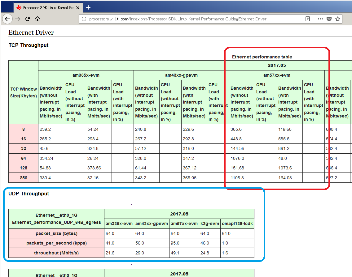
First of all I am studying TI's benchmark data as a reference, but it was not easy for me to understand the meaning of the values.
Can I ask what is the meaning of the values in the table?
Or let me make a specific questions:
- These values are transmit or receive ?
- The UDP tables looked easy to use. Why TCP table took the different format?
- Could I ask the operations to test TCP? Are they the lines on the bottom of UDP results?
iperf -s -u
iperf -c <server ip> -b <bandwidth limit> -f M -t 60
http://processors.wiki.ti.com/index.php/Processor_SDK_Linux_Kernel_Performance_Guide#Ethernet_Driver
↧
TMS570LS0432: VBUS cycles at the PBIST run
Part Number:TMS570LS0432
Hello,
When the PBIST runs (by the function pbistRun), in order to enable the PBIST controller, it sets the register MSTGCR=Ah. Well, since this is the last setting of that register, the field ROM_DIV contained in MSTGCR is set to 0h. It means that the ROM clock source is HCLK divided by 1. PBIST will reset for 16 VBUS cycles. Why is the implemented for-loop with 32 VBUS cycles instead ? (see the corresponding code below)
void pbistRun(uint32 raminfoL, uint32 algomask)
{
    volatile uint32 i = 0U;

/* USER CODE BEGIN (17) */
/* USER CODE END */

    /* Disable memory self controller */
    systemREG1->MSTGCR = 0x00000005U;

    /* Disable Memory Initialization controller */
    systemREG1->MINITGCR = 0x5U;

    /* Enable PBIST controller */
    systemREG1->MSINENA = 0x1U;

    /* Enable memory self controller */
    systemREG1->MSTGCR = 0x0000000AU;

    /* wait for 32 VBUS clock cycles at least, based on HCLK to VCLK ratio */
	/*SAFETYMCUSW 134 S MR:12.2 <APPROVED> "Wait for few clock cycles (Value of i not used)" */
	/*SAFETYMCUSW 134 S MR:12.2 <APPROVED> "Wait for few clock cycles (Value of i not used)" */
    for (i=0U; i<(32U + (32U * 0U)); i++){ /* Wait */ }

...
↧
TXB0104: TXB0104PWR
Part Number:TXB0104
Hi,
We are using TXB0104PWR in our design for translating signals from 3.3V to 5V. It includes a clock signal also. we may tune the frequency of the clock upto 50MHz.
So, I would like to know whether TXB0104PWR can be used for translating 50MHz signal or not.
If not, What could be the maximum frequency that it can support.
Warm Regards,
E.Rohini
↧
Linux/TIDEP-0097: GPS module and Drivers on Linux and Android
Part Number:TIDEP-0097
Tool/software: Linux
Dear TI Champs
The TI J6 entry TI design TIDEP-0097 has 2 GPS modules on it. isnt it?
Does it have the GPS Drivers on Linux and Android for
1. WL187x
2. Ublox GPS module.
Could you please share the link for the SDK that supports these drivers? Processor SDK for DRA7xx Data sheet or release notes or SW dev guide do not seem to clear this ambiguity.
BTW, what alternate DRA HW EVMs/ref designs support GPS HW and/or SW?
Thanks!
Best Regards
Feroz
↧
↧
ADS131A04EVM: Conversion involving third party SBC(RassberryPi and Arduino)
Part Number:ADS131A04EVM
Hi, I am using third party SBCs such as RassberryPi program in this link and Arduino program in this link to access ADS131A04EVM through SPI.
However, I am not sure on the hardware pin configuration.
Currently the RPi only gets the return with 0x0000s from SPI channel, which indicates that the communication is not set successfully (same as "not connect to any device").
I wonder what is the pin configuration (on JP, M0,M1,M2 ... etc) necessary for RPi-ADS131A04 system to send commands like UNLOCK(0x0655), RESET(0x0011) and WAKEUP (0x0033) through SPI.
Or there is any hardware configuration reference/guide for such system structure.
Thanks for the help. Kuo-Hsuan.
↧
LM25085: Low VIN condition
Part Number:LM25085
Hi,
Pgate voltage goes from Low to High after few ms from when VIN dropped below 4.5V as attached.
(Please visit the site to view this file)
Can we bring forward this rising edge?
Because we would like to drop VOUT(+5V) quickly.
Best Regards,
Kuramochi
↧
Compiler/DLP6500FLQ: Flip and invert
Part Number:DLP6500FLQ
Tool/software: TI C/C++ Compiler
Hi,
I am currently using pattern display in structured light mode. It should display one pattern and flip along long axis and then flip on short axis. This will give us different images.
I have created the batch file to display one image from flash and perform flipping and inversion, total 8 combinations.
However, it doesn't let me flip while executing this. I have to manually reset the DMD and execute the patterns again.
is there any way to flip and invert without resetting the DMD?
Regards
Chai
↧