Hi,
Does anyone have the distribution data of the TS5A3159-Q1 NC/NO OFF leakage current spec?
Thanks
Go
Hi,
Does anyone have the distribution data of the TS5A3159-Q1 NC/NO OFF leakage current spec?
Thanks
Go
Hello Sir,
I want to implement Ethercat stack on beaglbone black (am3358) to drive a Kollmorgen AKD servo drive. I am using TI SDK kit 7 with linux kernel 3.12. I checked the data sheet of am3358 and its written that there is Ethercat hardware support using PRU units.
Are there any libraries that I can use for Ethercat. Also Is there any tool (like molex for Ethernet/IP) to test the functionality.
Regards
Aditya
Hi,
We already porting 4AJ.1.1 on 1GB device and it is working fine.
And we got a new HW with 2GB RAM and it's work with 1GB code.
So I change some code in u-boot and x-loader
x-loader: sdram_elpida.c
__raw_writel(0x80740300, DMM_BASE + DMM_LISA_MAP_3);
__raw_writel(0x80720100, MA_BASE + DMM_LISA_MAP_0);
__raw_writel(0xFF020100, MA_BASE + DMM_LISA_MAP_1);
__raw_writel(0x00000000, MA_BASE + DMM_LISA_MAP_2);
__raw_writel(0x80740300, MA_BASE + DMM_LISA_MAP_3);
u-boot: cmd_bootm.c
strcat (bootarg, " mem=2040M ");
bootarg shows:
console=ttyO2,115200n8 androidboot.console=ttyO2 init=/init vram=64M omapfb.vram=0:32M consoleblank=0 mem=2040M
and remove ducati-m3.bin but still has problem with following message from kernel
[ 92.757507] init: cannot execve('/system/bin/mediaserver'): Accessing a corrupted shared library
[ 92.766845] Unable to handle kernel paging request at virtual address df8d1647
[ 97.839416] Unable to handle kernel paging request at virtual address df8d1647
[ 102.912506] Unable to handle kernel paging request at virtual address df8d1647
[ 107.986267] Unable to handle kernel paging request at virtual address df8d1647
[ 113.060668] Unable to handle kernel paging request at virtual address df8d1647
This seems to be a common question but I have not been able to find a complete answer.
What is the preferred method for flash programming in a production environment?
The wiki mentions a method, but says windows is not yet supported and there are a number of (Coming soon).
http://processors.wiki.ti.com/index.php/AM335x_Flash_Tool_User%27s_Guide
Any update or comments would be appreciated.
Thanks
Hi,
is there any examples on how to configure VFDC component to utilize RGB instead of YUV signals. Is this supported?
Thanks,
Danillo
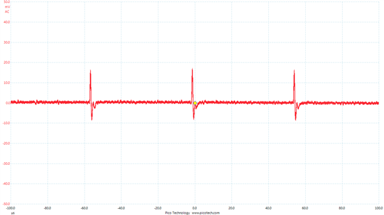
I am trying to use the DAC8831, and made a PCB based on the DAC8831EVM schematic. To test it, I supplied +/-5V and looked at the ouptut, which should be the result of the power-on reset. However, I saw a well-defined pattern, which I think is noise. See attached figure. The measurement was taken AC-coupled. After trying a few things, I decided to look at the DAC8831EVM, for reference. However, the same "noise" also exists on the DAC8831EVM output. I also tried changing the power supply, to ensure that the analog was supplied from a linear power supply, instead of a switching power supply. I also tried to ground !LDAC and pull-up !CS, which didn't have an effect. On the DAC8831EVM, the repeating pattern might go away when the switch is set to unipolar.
Would someone please help me understand what is going on, and whether it is possible to remove this noise signal? Is it actually noise? I am assuming it is noise because a 20mV signal compared to a 2V range would be around 8-bit resolution, far worse than the 16-bit resolution of this dac. I know that it is very difficult to get the full 16-bits, but I am hoping to do better than the current performance of 20mV out of 2.5V.
Can someone please help?
First, what I'm trying to do. I need a CC2541 to measure the pulse width of a train of pulses and load those into a buffer, but I don't know when those pulses will begin.
In the CC253x/4x User's Guide, in the I/O Ports section, on page79, it says:
"Even I/O pins configured as peripheral I/O or general-purpose outputs have interupts generated when enabled."
I've got it connected to a pin that is configured as Timer 4, channel 1 in capture mode. I've also got that pin's GPIO interrupt configure. Just to be clear, the pin isn't configured as a GPIO, but as a peripheral. I want the chip to interrupt on pin change, disable pin interrupts, then enable the timer interrupt. The timer interrupt will load each timer reading into a buffer, then set the clear timer pin, and wait till the next timer interrupt, and repeat till the timer is full. can I configure a pin as a timer, and still get GPIO interrupts if I've enabled both?
Hello,
I have a question from customer.
>Audio product : AV-Receiver
>Used Ti part : LM94022BIMG/NOPB
>Question :
How about information certification of LM94022?
Customer heard LM94022 is available UL60730-1 certification.
And customer want to process IEC60730-1 certification, because Anam product biz need for Europe market.
Eddy Lee(eddy.lee@avnet.com)
Hi,
I have an application where I need to time the duration between two events. The events do not necessarly fall on the same period every time (i.e. exectution time during the events can vary). The timer needs to be at least a 100 us per count resolution for the data to be useful. The 2 events will never occur more than .1 seconds apart.
Is there a way to start a dmtimer and simply read the value incremented within its counter? Or a way to get a high enough resolution time from the rtc? I would prefer a method that does not require me to set an interrupt and increment my own counter upon interrupt trigger as that creates needless overhead.
Thanks,
Eddie
The reason for the question is to determine whether there is a TI, MCU available that is sufficiently close to that implemented in the CC2538 to make direct use of the CC2538DK Contiki port, less radio driver. The aim being to substitute a CC1200 radio driver (based on an available CC1101 driver) to support a new sub GHz board.
So is the CC2538 MCU based on any other TI product?
Hopefully that makes sense. Would appreciate a TI (or any other) view on this.
Best wishes
Ron
I'm still attempting to work through the CC3200 Getting Started Guide and hopefully after uninstalling and re-installing CCSv6 from scratch (yet again), I might be able to build the wlan_station example and run it.
Looking forward to creating my own custom project, I'm presuming it will be much easier to simply "duplicate" one of the example projects and modify/add code to that. Is there a guide to this process anywhere? One of the main issues/problems I see with the process:
I want to copy an example project from C:\ti\cc3200-sdk\examples\ to my own project directory - what is the easiest way to resolve the reference issues?
Anyone have a cheat sheet on how to do this?
Thanks,
Craig
Dear Sir,
i have installed Cc3200 SDK 1.0 and found many example code, now I want to implement a GPIO ISR into "Out of Box" code, objective is drive cc3200 entry smart configuration mode by a GPIO, but I cannot found a GPIO Interrupt example code in the SDK, any advise?
BR
Edwin
I find a IPC example project . in the project core0 triger ipc interrupt to core1.
and core1 trogers ipc interrupt to core2,and so on.i have no EVM board and this project is run under simulator mode.
I defined a glbal variable 'int g_flag = 3'.In the correspondig ipc_isr function, i added one to g_flag and
print its value in console.
however the output message is below , it looks as if the global variable added only once . it means the variable is not shared by all the eight cores.
how to define and use a global variable that can be operated by all cores on DSP6678 under IPC ?thanks.
Set interrupt from Core 0 to Core 1, cycle = 1053673622
Interrupt Info 0
[TMS320C66x_1] Receive interrupt from Core 0 with info 0x0, cycle = 1057016594
g_flag = 4
Set interrupt from Core 1 to Core 2, cycle = 1057033058
Interrupt Info 8
[TMS320C66x_2] Receive interrupt from Core 1 with info 0x0, cycle = 1059235265
g_flag = 4
Set interrupt from Core 2 to Core 3, cycle = 1059251792
Interrupt Info 16
[TMS320C66x_3] Receive interrupt from Core 2 with info 0x10, cycle = 1057523984
g_flag = 4
Set interrupt from Core 3 to Core 4, cycle = 1057540624
Interrupt Info 24
[TMS320C66x_4] Receive interrupt from Core 3 with info 0x10, cycle = 1060312891
g_flag = 4
Set interrupt from Core 4 to Core 5, cycle = 1060329531
Interrupt Info 32
[TMS320C66x_5] Receive interrupt from Core 4 with info 0x20, cycle = 1060791800
g_flag = 4
Set interrupt from Core 5 to Core 6, cycle = 1060808440
Interrupt Info 40
[TMS320C66x_6] Receive interrupt from Core 5 with info 0x20, cycle = 1066910801
g_flag = 4
Set interrupt from Core 6 to Core 7, cycle = 1066927441
Interrupt Info 48
[TMS320C66x_7] Receive interrupt from Core 6 with info 0x30, cycle = 1070451703
g_flag = 4
Set interrupt from Core 7 to Core 0, cycle = 1070468343
Interrupt Info 56
[TMS320C66x_0] Receive interrupt from Core 7 with info 0x30, cycle = 1065998385
g_flag = 4
IPC test passed!
Hello,
What is the method for moving ethernet into low power ? Is it a matter of changing the power domain (register) ?
Thanks,
Ran
I'm a bit of a newbie to convertors so this might be a daft question.
I have two different unregulated but rectified voltage sources (permanent magnet generators) 3 to 20+ vdc and I would like to tie them in parallel in order to charge a battery or provide lighting. I thought that providing a voltage regulator on each would help. However, as the output voltage on each may not be exactly the same I could end up with regulator shutdown and/or one potentially never charging the battery. Diodes and/or balancing resistors might help, but I'm not sure if this is the way to go as each have losses.
Alternatively, given that the voltage on one could be lower for some considerable time I could either have to store/release it somehow or lose the available energy. Given that the project is to harvest as much power from each source as possible, this is an issue of efficiency.
I also thought about using a charge pump on each paralleled generator after each regulator to deliberately 'pump' output alternately as the others voltage reduced. But again, I'm not sure of the issues involved.
Please can you provide some guidance as the best approach?
Thanks for your help.
I would like to disconnect with the mobile device when nothing happens for 30s. After the device is disconnected it should start advertising again. I know there is the GAPRole_TerminateConnection(); function to disconnect with the mobile device.
But how can I set up this with 30s? Is there a function like TimeOutConnection or something similar where i can set parameters for time to disconnect?
Hi all,
We are using BQ34Z110 fuel gauge in one of our designs to operate with a 12V 7AH lead acid battery. We have completed the configuration,calibration part & now want to run a optimization cycle.
The problem we are facing is that when we send a IT_enable command, only QEN flag is getting set, but VOK flag is always zero.
Below post suggests 3 conditions for VOK to be set: http://e2e.ti.com/support/power_management/battery_management/f/180/t/159009.aspx
In our case
1) dV/dT<4uV/sec holds good since there is no change in measured voltage.
2) Voltage measured is outside disqualification window
3) Temperature is 31.8C
With all these conditions, sending IT_enable command is not setting the VOK flag even though update status register reads 0x04.
Below are the snapshots of DATARAM registers both before & after sending IT_enable command.
Before Sending IT_Enable :
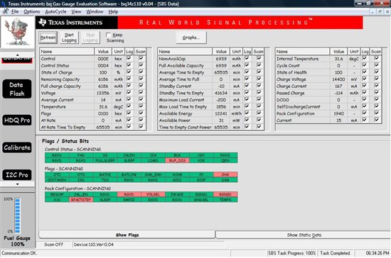
After sending IT_Enable :
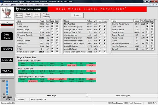
One more observation is that, the RUP_DIS flag is always "1" & OCVTAKEN is "0".
For VOK flag to set is there a need of OCVTAKEN being "1" ?
Average current is 16mA and we have set quit current to be 40mA. Thus battery should be in relaxation mode.
Is our assumption correct?
Please suggest.
Thanks,
Suresha N S
Dear Friends,
I'm a newbie to C2000 MCU's, as I'm trying to run the adc peripheral, I tried to use the sample code on Controlsuit, but when I connect my signal generator (10H sin wave, 1V pk-pk) to either ADCINA4 or ADCINA2, I can not see any change in the watch window, or the Single time graph. I'm using CCS v5. Could you help me on how to solve the problem?
Thank you indeed
//#############################################################################
//
// File: f2802x_examples_ccsv4/adc_soc/Example_F2802xAdcSoc.c
//
// Title: F2802x ADC Start-Of-Conversion (SOC) Example Program.
//
// Group: C2000
// Target Device: TMS320F2802x
//
//! \addtogroup example_list
//! <h1>ADC Start-Of-Conversion (SOC)</h1>
//!
//! Interrupts are enabled and the ePWM1 is setup to generate a periodic
//! ADC SOC - ADCINT1. Two channels are converted, ADCINA4 and ADCINA2.
//!
//! Watch Variables:
//!
//! - Voltage1[10] - Last 10 ADCRESULT0 values
//! - Voltage2[10] - Last 10 ADCRESULT1 values
//! - ConversionCount - Current result number 0-9
//! - LoopCount - Idle loop counter
//
// (C) Copyright 2012, Texas Instruments, Inc.
//#############################################################################
// $TI Release: LaunchPad f2802x Support Library v100 $
// $Release Date: Wed Jul 25 10:45:39 CDT 2012 $
//#############################################################################
#include "DSP28x_Project.h" // Device Headerfile and Examples Include File
#include "f2802x_common/include/adc.h"
#include "f2802x_common/include/clk.h"
#include "f2802x_common/include/flash.h"
#include "f2802x_common/include/gpio.h"
#include "f2802x_common/include/pie.h"
#include "f2802x_common/include/pll.h"
#include "f2802x_common/include/wdog.h"
// Prototype statements for functions found within this file.
interrupt void adc_isr(void);
void Adc_Config(void);
// Global variables used in this example:
uint16_t LoopCount;
uint16_t ConversionCount;
uint16_t Voltage1[10];
uint16_t Voltage2[10];
ADC_Handle myAdc;
CLK_Handle myClk;
FLASH_Handle myFlash;
GPIO_Handle myGpio;
PIE_Handle myPie;
PWM_Handle myPwm;
void main(void)
{
CPU_Handle myCpu;
PLL_Handle myPll;
WDOG_Handle myWDog;
// Initialize all the handles needed for this application
myAdc = ADC_init((void *)ADC_BASE_ADDR, sizeof(ADC_Obj));
myClk = CLK_init((void *)CLK_BASE_ADDR, sizeof(CLK_Obj));
myCpu = CPU_init((void *)NULL, sizeof(CPU_Obj));
myFlash = FLASH_init((void *)FLASH_BASE_ADDR, sizeof(FLASH_Obj));
myGpio = GPIO_init((void *)GPIO_BASE_ADDR, sizeof(GPIO_Obj));
myPie = PIE_init((void *)PIE_BASE_ADDR, sizeof(PIE_Obj));
myPll = PLL_init((void *)PLL_BASE_ADDR, sizeof(PLL_Obj));
myPwm = PWM_init((void *)PWM_ePWM1_BASE_ADDR, sizeof(PWM_Obj));
myWDog = WDOG_init((void *)WDOG_BASE_ADDR, sizeof(WDOG_Obj));
// Perform basic system initialization
WDOG_disable(myWDog);
CLK_enableAdcClock(myClk);
(*Device_cal)();
//Select the internal oscillator 1 as the clock source
CLK_setOscSrc(myClk, CLK_OscSrc_Internal);
// Setup the PLL for x10 /2 which will yield 50Mhz = 10Mhz * 10 / 2
PLL_setup(myPll, PLL_Multiplier_10, PLL_DivideSelect_ClkIn_by_2);
// Disable the PIE and all interrupts
PIE_disable(myPie);
PIE_disableAllInts(myPie);
CPU_disableGlobalInts(myCpu);
CPU_clearIntFlags(myCpu);
// If running from flash copy RAM only functions to RAM
#ifdef _FLASH
memcpy(&RamfuncsRunStart, &RamfuncsLoadStart, (size_t)&RamfuncsLoadSize);
#endif
// Setup a debug vector table and enable the PIE
//PIE_setDebugIntVectorTable(myPie);
PIE_enable(myPie);
// Register interrupt handlers in the PIE vector table
PIE_registerPieIntHandler(myPie, PIE_GroupNumber_10, PIE_SubGroupNumber_1, (intVec_t)&adc_isr);
// Initialize the ADC
ADC_enableBandGap(myAdc);
ADC_enableRefBuffers(myAdc);
ADC_powerUp(myAdc);
ADC_enable(myAdc);
ADC_setVoltRefSrc(myAdc, ADC_VoltageRefSrc_Int);
// Enable ADCINT1 in PIE
PIE_enableAdcInt(myPie, ADC_IntNumber_1);
// Enable CPU Interrupt 1
CPU_enableInt(myCpu, CPU_IntNumber_10);
// Enable Global interrupt INTM
CPU_enableGlobalInts(myCpu);
// Enable Global realtime interrupt DBGM
CPU_enableDebugInt(myCpu);
LoopCount = 0;
ConversionCount = 0;
// Configure ADC
//Note: Channel ADCINA4 will be double sampled to workaround the ADC 1st sample issue for rev0 silicon errata
ADC_setIntPulseGenMode(myAdc, ADC_IntPulseGenMode_Prior); //ADCINT1 trips after AdcResults latch
ADC_enableInt(myAdc, ADC_IntNumber_1); //Enabled ADCINT1
ADC_setIntMode(myAdc, ADC_IntNumber_1, ADC_IntMode_ClearFlag); //Disable ADCINT1 Continuous mode
ADC_setIntSrc(myAdc, ADC_IntNumber_1, ADC_IntSrc_EOC2); //setup EOC2 to trigger ADCINT1 to fire
ADC_setSocChanNumber (myAdc, ADC_SocNumber_0, ADC_SocChanNumber_A4); //set SOC0 channel select to ADCINA4
ADC_setSocChanNumber (myAdc, ADC_SocNumber_1, ADC_SocChanNumber_A4); //set SOC1 channel select to ADCINA4
ADC_setSocChanNumber (myAdc, ADC_SocNumber_2, ADC_SocChanNumber_A2); //set SOC2 channel select to ADCINA2
ADC_setSocTrigSrc(myAdc, ADC_SocNumber_0, ADC_SocTrigSrc_EPWM1_ADCSOCA); //set SOC0 start trigger on EPWM1A, due to round-robin SOC0 converts first then SOC1
ADC_setSocTrigSrc(myAdc, ADC_SocNumber_1, ADC_SocTrigSrc_EPWM1_ADCSOCA); //set SOC1 start trigger on EPWM1A, due to round-robin SOC0 converts first then SOC1
ADC_setSocTrigSrc(myAdc, ADC_SocNumber_2, ADC_SocTrigSrc_EPWM1_ADCSOCA); //set SOC2 start trigger on EPWM1A, due to round-robin SOC0 converts first then SOC1, then SOC2
ADC_setSocSampleWindow(myAdc, ADC_SocNumber_0, ADC_SocSampleWindow_7_cycles); //set SOC0 S/H Window to 7 ADC Clock Cycles, (6 ACQPS plus 1)
ADC_setSocSampleWindow(myAdc, ADC_SocNumber_1, ADC_SocSampleWindow_7_cycles); //set SOC1 S/H Window to 7 ADC Clock Cycles, (6 ACQPS plus 1)
ADC_setSocSampleWindow(myAdc, ADC_SocNumber_2, ADC_SocSampleWindow_7_cycles); //set SOC2 S/H Window to 7 ADC Clock Cycles, (6 ACQPS plus 1)
// Enable PWM clock
CLK_enablePwmClock(myClk, PWM_Number_1);
// Setup PWM
PWM_enableSocAPulse(myPwm); // Enable SOC on A group
PWM_setSocAPulseSrc(myPwm, PWM_SocPulseSrc_CounterEqualCmpAIncr); // Select SOC from from CPMA on upcount
PWM_setSocAPeriod(myPwm, PWM_SocPeriod_FirstEvent); // Generate pulse on 1st event
PWM_setCmpA(myPwm, 0x0080); // Set compare A value
PWM_setPeriod(myPwm, 0xFFFF); // Set period for ePWM1
PWM_setCounterMode(myPwm, PWM_CounterMode_Up); // count up and start
// Wait for ADC interrupt
for(;;)
{
LoopCount++;
}
}
interrupt void adc_isr(void)
{
//discard ADCRESULT0 as part of the workaround to the 1st sample errata for rev0
Voltage1[ConversionCount] = ADC_readResult(myAdc, ADC_ResultNumber_1);
Voltage2[ConversionCount] = ADC_readResult(myAdc, ADC_ResultNumber_2);
// If 10 conversions have been logged, start over
if(ConversionCount == 9)
{
ConversionCount = 0;
}
else ConversionCount++;
// Clear ADCINT1 flag reinitialize for next SOC
ADC_clearIntFlag(myAdc, ADC_IntNumber_1);
// Acknowledge interrupt to PIE
PIE_clearInt(myPie, PIE_GroupNumber_10);
return;
}
Hi All,
I am new to use TI-RTOS. I have a bit confusion about HWI, SWI and TASK. Because I have some experience of using FreeRTOS-like RTOSes, so for the TASK I have no problem to understand it in TI-RTOS. But the two concepts 'SWI' and 'HWI', I cannot understand them well.
According to some references, I know HWI and SWI use the same C STACK (system STACK). Both of them cann't be blocked until they complete there execution. And both of them have priorities. The low priority HWI/SWI can be preempted by high priority HWI/SWI.
And HWI is essentially some C callback functions called in ISR function.
But I don't know where the TI-RTOS schedules SWIs. From the study vedio of TI-RTOS SWI, it pointed that
SWI function is also scheduled in ISR function. See below picture 'run any posted Swis'.

Above is my understanding about the scheduling of HWI and SWI. Please correct me if I'm wrong.
Thanks and Best Regards.
Brian.
Hi everyone,
So i was wondering what are the problems of importing or creating a Energia sketch to CCS. It uses GCC which i also don't know the difference from GCC to the other CCS compiler.
I really like using this because i normally have the hardest time in adding the file paths to the linker, so much that i almost want to just program in assembly.