Quantcast
Channel: Forums - Recent Threads
Viewing all 262198 articles
Browse latest View live

Concatenation with ";" in macro does not create a valid token

$
0
0

Hello,

I trying to compile some code that compiles in IAR on CCS. I have most of it working now, but I am getting a pre-processors error on a concatenation. This is the define

#define MCU_IO_INPUP(port, pin, func) st( P##port##SEL &= ~BIT##pin##; P##port##DIR &= ~BIT##pin##; )

This is the line that causes the error: ( I have 100 lines exactly the same causing the same error)

MCU_IO_INPUT(HAL_BOARD_IO_BTN_1_PORT, HAL_BOARD_IO_BTN_1_PIN, MCU_IO_TRISTATE);

I get a compiler error that says the ":" does not create a valid token.

Regards,
/Thomas


About the cascade connection of TUSB8020B.

$
0
0

Can TUSB8020B be used by cascade connection?
(Or stackable connection)

Best regards,

Satoshi

OMAP-L138 Secure Boot

$
0
0

Hi,

I am wanting to have the boot image for a L138 device encrypted to AES-128. I understand that using AIS boot mode supports encryption, and we are currently booting fine with unencrypted AIS boot images. From my understanding, I need a "High Security" device, and the SecureHexAIS tool in order to implement encryption (Processor Security User Guide SPRUGQ9, Page 27). I have installed the program, but there is very little documentation describing what to do in order to implement the encryption. Additionally, the only files I see in the directory after installation are:

C674x_OMAPL1x_Generic_Security_Flash_Boot_Utils.tar.gz

Manifest_Secure_C674x_OMAP-L1x Flash and Boot Utils.pdf

OMAPL138_C6748_Generic_Security_Users_Guide_v1.0.2.pdf

And uninstall.exe

I unpacked the tar.gz (What kind of installer doesn't unpack files anyways?) and was able to find the tool, but when using the SecureHexAIS_OMAP-L138.exe with the example ini. I receive an error stating that the program could not find key_hdr_sha256_enc.bin.

I feel like somehow I downloaded a incomplete/broken toolset, especially since I had to unpack the files. Any thoughts/ideas? I am new, so it may be entirely my fault.

Thanks,

Joe 

TAS5630B failures

$
0
0

We are running the TAS5630B in a BTL configuration with BD modulation.  The circuitry is the same as the reference circuit in the data sheet except the output inductors are 10 uH (instead of 7 uH) and the output capacitors are 0.680 uF (instead of (0.470 uF).  It is designed to operate into a 6 Ohm load with a Q=0.70.  The supply voltage is 26-37 VDC and the housekeeping supply is 11.7 VDC.  Both are well filtered.

We have observed a number of chip failures, where the "ready" line never goes high and it appears that one or more of the output FETs are blown.  The circuit has often worked for some period of time (minutes to hours) before the spontaneous failure.  The output power has always been quite low (10 Watts/channel or less) and at times with no input signal at all. 

We configure the amplifier as a constant voltage amplifier with an autotransformer to step up the voltage from 25 V to 70 V.  A high impedance speaker is connected to the autotransformer output.  Has anyone observed such failures?  Are any circuit topology or component value changes needed to accommodate the autotransformer?

DMD Operation

$
0
0

Hi, I am a graduate student working on a project. I have a question on the operation of DMD in a DLP Projector.

I made a powerpoint slide with a black background and just a white star at the center. I connected the computer to the DLP projector and instead of a mercury vapor lamp I used a laser pointer (used in presentations) as the light source. The beam diameter was only about 40% of the DMD chip area. I also removed the optics that focus the image after the DMD chip. What I noticed was strange. Instead of just one star which I was supposed to get on the output end, I was getting an array of them. 

So my question is, does the DMD in normal operation form multiple images in the micro-mirrors and then focuses all through the optics? Or Something else?

Waiting for your reply! :)

Thanks in advance!

Azhar

CC Debugger Not Recognized After Firmware Upgrade

$
0
0

I have the latest version of SmartRF Flash Programmer, and two new CC Debuggers out of the box.  When I plug in the CC Debugger to USB, SmartRF tells me it needs to updgrade the firmware, not unexpected.  I change "What do you want to program?" to Program Evaluation Board, the EB Application (USB) tab says:

EB ID 4427, Chip type NA, EB firmware ID 05CC, EB firmware rev 0027 (note this is what it says now after flashing)  The Flash image is:

C:\Program Files (x86)\Texas Instruments\SmartRF Tools\Flash Programmer\bin\..\..\Firmware\CC Debugger\cebal_fw_srf05dbg.hex

The box nder Perform Actions says it completed successfully. HOWEVER, when I change What do you want to program? to "Program CCxxxx SoC...", it does not recognize the CC debugger any more.  The SOC box is blank.  I get the correct beeps from the PCB when I plug and unplug the CC debugger, and I can go back to program evaluation board and it sees it, but it's never recognized for programming.  I tried my second CC Debugger, and got the exact same issues and result.

Can anyone suggest how to get this to work?  The LED on the CCD just stays red, even after I plug in the target board and processor.

DK-TIVA4C129x TMP100 sensor I2C

$
0
0

Hi,

I have Tiva4C129x development kit. It has TMP100 temperature sensor which has I2C.

My purpose is to learn I2C and read the temperature from the sensor.

I have wrote a dummy code which explains the procedure in which one should configure I2C and start the communication.

SCL and SDA is located on PB6 and PB7 on TIVA. Also it uses I2C6 module which is connected to TMP100.

I have read the datasheet of both device and from that what I have understood I wrote the code.

Please note that I'm just focusing on the procedure and dont worry about debugging the code right now. I'm using 25MHz crystal.

I'm bit confused in configuring the TMP100 registers. It has 5 registers in total. Pointer Reg, Configuration Reg, Temperate High and Low Reg, Temperature Register. The last one stores the conversion result.

Also I'm not sure if I'm waiting for acknowledgement correctly or not. Please correct me if I'm wrong.

Here is the code.

#include <stdbool.h>
#include <stdint.h>
#include "inc/hw_i2c.h"
#include "inc/hw_ints.h"
#include "inc/hw_memmap.h"
#include "inc/hw_types.h"
#include "driverlib/gpio.h"
#include "driverlib/i2c.h"
#include "driverlib/interrupt.h"
#include "driverlib/pin_map.h"
#include "driverlib/sysctl.h"

#define SLAVE_ADDRESS 0x4A
void main()
{
	SysCtlClockSet(SYSCTL_SYSDIV_1 | SYSCTL_USE_OSC | SYSCTL_OSC_MAIN |
                   SYSCTL_XTAL_25MHZ);
				   
	SysCtlPeripheralEnable(SYSCTL_PERIPH_I2C6);
	
	SysCtlPeripheralEnable(SYSCTL_PERIPH_GPIOB);
	
	GPIOPinConfigure(GPIO_PB6_I2C6SCL);
    GPIOPinConfigure(GPIO_PB7_I2C6SDA);
	
	GPIOPinTypeI2CSCL(GPIO_PORTB_BASE, GPIO_PIN_6);
    GPIOPinTypeI2C(GPIO_PORTB_BASE, GPIO_PIN_7);
	
	I2CMasterInitExpClk(I2C6_BASE, SysCtlClockGet(), false);	//initialization of master module
	I2CMasterSlaveAddrSet(I2C6_BASE, SLAVE_ADDRESS, true);		//sets the slave address and indicate that the master is reading from slave
	
	I2CMasterDataPut(I2C6_BASE, 0x01);					//P1 P0 = 01 = configuration reg. Byte goes to PR
	while(I2CMasterBusy(I2C6_BASE));    //is it correct?
	I2CMasterDataPut(I2C6_BASE, 0xA1);					//sets the bits of configuration reg. A1 = 10 bit, shutdown, OS=1 start conv. Byte goes to Config Reg
	while(I2CMasterBusy(I2C6_BASE));
	
	I2CMasterSlaveAddrSet(I2C6_BASE, SLAVE_ADDRESS, true);	//selects the pointer reg
	while(I2CMasterBusy(I2C6_BASE));	
	I2CMasterDataPut(I2C6_BASE, 0x03);					//P1P0= 11 = Temp high reg. Byte goes to PR
	while(I2CMasterBusy(I2C6_BASE));	
	I2CMasterDataPut(I2C6_BASE, 0x640);					//sets the Thigh reg = 100C. Byte goes to Thigh
	
	I2CMasterSlaveAddrSet(I2C6_BASE, SLAVE_ADDRESS, true);	//selects the pointer reg
	while(I2CMasterBusy(I2C6_BASE));	
	I2CMasterDataPut(I2C6_BASE, 0x02);					//P1P0= 10 = Temp low reg. Byte goes to PR
	while(I2CMasterBusy(I2C6_BASE));	
	I2CMasterDataPut(I2C6_BASE, 0x640);					//sets the Tlow reg = -25C. Byte goes to Tlow
	while(I2CMasterBusy(I2C6_BASE));	
	
	I2CMasterSlaveAddrSet(I2C6_BASE, SLAVE_ADDRESS, true);  //selects the pointer reg
	while(I2CMasterBusy(I2C6_BASE));	
	I2CMasterDataPut(I2C6_BASE, 0x00);					//P1P0= 00 = Temp high reg. Byte goes to PR
	while(I2CMasterBusy(I2C6_BASE));	
	data_low = I2CMasterDataGet(I2C6_BASE);						//receives the bytes from slave
	data_high = I2CMasterDataGet(I2C6_BASE);
	while(I2CMasterBusy(I2C6_BASE));	

}

I hope the I have given enough information, if not please let me know. 

Again I'm more interested to know about the procedure rather than worrying about the code itself.

Any help is much appreciated. thanks
DP83630 Precision PHYTER - 10BASE-T LOOPBACK ISSUE

$
0
0

Hi,

We are using DP83630 in our products. And now  we found an issue when we connect to a 10BASE-T HUB and always got bad packets (BAD CRC)  in MAC. By checking the setting in DP83630, we found that the bit LOOPBACK_10_DIS in 10BTSCR is 0, which means that the 10BT loopback is enabled.  After disable this LOOPBACK, no bad packets any more.

Normally, this LOOPBACK should not be enabled by default.  My question is whether there is an easy way to disable this LOOPBACK by default? and how?

Thanks.


Serial Bootloader (SBL) on CC2540 not working

$
0
0

Hello,

I am trying to use the serial bootloader (SBL) on the CC2540 with the physical UART interface (meaning I would have to connect some wires to the headers and use some external device to serve an image to update the CC2540 over UART). For CC2540, any form factor is OK for me, no matter it is  CC2540 EM or CC2540 keyfob or CC2540 USB dongle. I am currently using windows PC + CC2540 USB dongle to do prototype work. My eventual goal is to load image from Linux host to update the CC2540  over UART.

I followed the instruction from http://processors.wiki.ti.com/index.php/SerialBootLoader to first build SBL HEX file from C:\Texas Instruments\BLE-CC254x-1.4.0\Projects\ble\util\SBL\iar\cc254x. Then I used CCDebuger to load SBL_CC254xF256_UART0_ALT1.hex onto the CC2540 USB dongle. However, as soon as the SBL HEX is loaded onto CC2540 USB dongle, the USB dongle can no longer be recognized by windows PC as CC2540  USB CDC Serial Port. I suspect that UART HW doesn’t work at all on the USB dongle. I also connected the RX/TX/Ground pins (P0_2, P0_3, Ground respectively) of USB dongle to the computer from the TTL converter and used SBL Demo application to load .bin file to it , but comes up with the status "Timeout waiting for response from target".

As I mentioned, I don’t care CC2540 form factor, as long as it is CC2540. Can someone tell me how I can make SBL work on CC2540? Many thanks!

CC3200 with Camera - Where to Get CC3200 Camera Booster Pack Rev 3.0...

$
0
0

Good morning folks, 

I am interested in building the Camera application as desricbed here: 

http://processors.wiki.ti.com/index.php/CC32xx_Camera_Application

This seems to be a great way to get started with a Camera app.  The MT9D111 (or equivalent) can be easily found (eBay for example).  But I can't even find a listing for the CC3200CAMBOOST board that appears in the photo at that linked site.  Also, it appears that there are some sky wires on that Booster board. 

Does anyone know if this will soon be available for purchase? 

Many thanks!  Best, 

Eric

Signal and bias levels suitable for LMH6882

$
0
0

Hi,

We are currently debugging a new ADC-based design and we are using an LMH6882 variable gain amplifier to fine-tune the incoming analogue signal. However we are finding that the output amplitude from the LMH6882 is far lower than what we have simulated. I've attached a PDF of the current circuit.


Could someone comment on how we've biased and set the feedback for this circuit?

Thanks,

Eoin

(Please visit the site to view this file)

When Bluetopia can support prepared write?

$
0
0

Apple's new HomeKit will be a big push to BLE enabled devices.

However it requires "prepared write up to 512byte"

We really hope SS1 can releae the long expected feature.

LM5107bootstrap cap

$
0
0

Hello

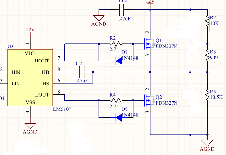
I intend to use the LM5107 in a new design.  The circuit topology is relatively straightforward, or so it seems.

I'm looking to swing the common node (source of Q1, drain of Q2) at low frequency from the DC bias point of ~6V to the top rail 12V and then some time later to the bottom rail AGnd then back to neutral.  See pic below.

The LM5107 is not working as expected.  The high-side fet is not turning on.  The data sheet does not state when/how the bootstrap cap is charged and I suspect that's the root of the issue.  I've checked layout, part values, footprints etc..  When both HIn and LIn are low, both fets are off as expected and the bootstrap cap (HS pin) sees the 6V bias. When the low side FET is on, the cap sees 0V as expected.  The high side FET never turns on and the waveform at HOUT is odd.  The bootstrap cap value is 1uF.  I tried .47uF as well.  The time either FET is 'on' is around 3us, 'off' otherwise.

Any one have any experience with either half-bridge circuits in general or this particular part please??  I don't see why this circuit is so fussy...  

Is it the DC bias point causing issues?

Does the cap charge when the low-side FET is on?  Or, does it simply follow the voltage on the common node?  If that is true, then it should just charge to 12V - 6V = 6V right?  Then, the voltage on the high side gate should be the 6V cap voltage + 12V supply = 18V??  The FET should turn on....

CDCE62005 / CDCE62002 to HCSL

DAC5682Z Dual-Channel Interleaving

$
0
0

Hi,

I am using DAC5682Z for RF application.

The setting is Dual Dac (IQ and Interleaver mode is on), 4x interpolation, mix0=lp, mix1=fs/4.

My questions are the following:  

According to DAC5682Z datasheet on pg3, on pin description for D[15..0]P, it says "In dual-channel mode, data for the A-channel is input while DCLKP is high"

  1. so I assume that in dual channel mode, B-channel is the input while DCLKP is low or DCLKN is high. is it true?
  2. in this case, B channel data is offset by 1/2 clock rate. is it true?

Thanks

-Kyle


BQ27742 -- Impedance Track suitability for long term charge

$
0
0

Hi Team,

I have an application where a single charge in a pack is expected to last 7 to 8 years in a device that is located outdoors which means it will be subject to seasonal temperature fluctuations.

Would the DOD, SOC, or TTE values fluctuate drastically due to pack temperature? 

The concern is, if the gas gauge is queried in the summer, it will give a different TTE/DOD/SOC than if it is queried in the winter.

Also, is there a way to disable under-voltage protection for the bq27742 device?


Regards,

About clock programming software for CDCE706

$
0
0

Hi,

I have a question about clock programming software for CDCE706.

At production web page of CDCE706, there are following two software:
http://www.ti.com/product/CDCE706/toolssoftware
1.TI-Pro-Clock Programming Software(Rev.F)
2.ClockPro(TM) Programming Software

Is this two software same and possible to program CDCE706?

I understood that Pro-Clock is software for programming CDCE706.
But Pro-Clock doesn't support Win7 so that if ClockPro and Pro-Clock
is same software , I want to use ClockPro because it supports Win7 and our OS is Win7.

best regards,
g.f.

MuxIt Frequency Multiplier SN65LVDS150PW

$
0
0

I am looking at this device to extend the utility of a cheap AD9850-based radio VFO.

I want to convert the output to I/Q by multiplying it and then dividing by 4 with a D-flip flop circuit

Since this multiplier has so many ranges of multiplication, I could also extend the frequency range of my VFO

<\p>

Will this device stay locked as I change the clock frequency?

Does this device need to be fed with a squared-off clock signal or is sine ok?

Any other words of advice?

+/-15VDC supply from 48VDC

$
0
0

I am hoping to make a 48VDC to +/-15VDC power supply. The LMZ34003 does not say whether it is isolated. Is there some way to us use two of them, one for + 15 and the other for the -15? 

TI ARM compiler - acpia470.exe : INTERNAL ERROR: acpia470.exe experienced a segmentation fault while processing

$
0
0

Team,

The following error has been reported. Some more details (Compiler version, log message, ..etc) will be added soon:

"I have just updated to CCS V5.1 RC 2. When I try to compile my OMAP_L137 project (ARM core) I get the following error message:
INTERNAL ERROR: C:\Tools\TI\ccsv5\tools\compiler\tms470\bin\acpia470.exe experienced a segmentation fault while processing"

Thanks and best regards,

Anthony

Viewing all 262198 articles
Browse latest View live


<script src="https://jsc.adskeeper.com/r/s/rssing.com.1596347.js" async> </script>