Quantcast
Channel: Forums - Recent Threads
Viewing all 262198 articles
Browse latest View live

evaluation board for MSP430F5232

$
0
0

Hi, 

I am going to use MSP430F5232 for my design, and I need to purchase its evaluation board.

What I could find is MSP-FET430U64C. It seems to be a good candidate, but it is for 64-pin package.

I have two questions.   

1. Do you have an evaluation board only for MSP430F5232 (48-pin package)?

2. If not, what evaluation board do you recommend?

Thank you. 


TMS570LS3137 PBIST self check from HALCoGen 3.06

$
0
0

Hello,

As part of pbistSelfCheck() in sys_selftest.c, HALCoGen generates the following code:

/* Start PBIST */pbistREG->DLR=0x14U;

This violates the SPNU499 description of the Datalogger Register DLR which says do not change bit 3 from its default value of 1. 

Which is correct?

Thanks, Charlie Johnston


PWM Code not running correctly after reset

$
0
0

I have code on the F28M35x outputting basic PWM waveforms. However, when I stop debugging and power cycle the board, the output is no longer correct. I then get a few pulses spread out much further in time, as if the PWM switching frequency were reduced significantly.

I believe I did not have this problem previously. However, I have not changed anything that I think would cause this issue. My code is linked to flash memory:

   .cinit              : > FLASHA      PAGE = 0
   .pinit              : > FLASHA,     PAGE = 0
   .text               : > FLASHA      PAGE = 0

On the Debug Configuration screen, under the Target tab, there is an Auto Run and Launch Options settings page. I have tried checking "On a reset" under "Auto Run Options", but then the debugger does not load code onto the board.

So the question is: Why might my code be running incorrectly out of a reset when it runs correctly out of the debugger?

Incorrect readings from the ADS1110

$
0
0

Hi,

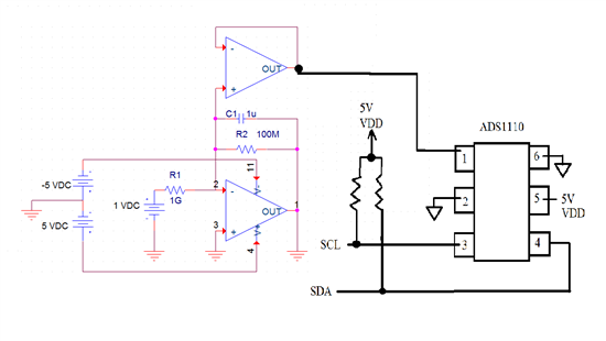
I am using the ADS1110 via the I2C protocol to read voltages coming from an OP AMP (LMC662), but I noticed that the result is constantly 0.2V, which is incorrect, while the results coming from the analog pin of my microcontroller are correct. The ADS1110 will read voltages from a 10k ohm potentiometer just fine so I know it is working. Therefore, I assume it is a high output/low input impedance issue so I tried inserting a buffer in between the OP AMP and the ADS1110 but the buffer somehow amplified the voltage to 1.6V. The OP AMP I am using as the buffer is the LM324N.

Here is the schematic

I am not sure where to go from here.

Regards

Bunnarong

DAC7678 Channel-F problem

$
0
0

Hi, we are using a VQFN DAC7678 in a board. All channels work perfectly except the F one, which does not put voltages above 3.5V in his output. With the same code, the other channels put voltages over the entire range of the chip (0 to 5V).

In the F channel, codes until 3.5V works fine, but above that it's like there would be some kind of clamp... I have isolated the F-output to discard effects of the following analog parts but the problem persists

Please can you help in any way?

Usb Spike Issues

$
0
0

Hi ,

I have been using Stellaris Lm3s5951 ic for my applications. but now i wish to migrate to TIVA. While using stellaris while i connect a keyboard to the USB port  ,the system works fine until any external spikes come via USB.

In presence of an external unwanted EMF spikes the system behaves abnormally .Sometimes  the system hangs and needs to be reset .Is there any solution for this problem ????

Does TIVA take care of such situations???

Regards,
Dhanush

AFE44x0SPO2EVM interface to External MCU

$
0
0

Is it possible to interface the AFE44x0SPO2EVM to an external MCU development board?

Reference Schematic of TS3DV520E

$
0
0

Hi~

Our customer want reference schematic for TS3DV520E device.

Please support schematic...


Questions regarding power and clock of MSP430f5232.

$
0
0

Hi, 

I have several questions on the power and clock of MSP430F5232. 

  1. I could not find a reference design with MSP430F5232. Is there a reference design? I want to check how clocks and powers are provided in the reference design.  
  2. Power: For MSP430F5232, all three powers VCC/AVcc/DVcc are tied together with two capacitors of 10uF and 0.1uF according to the reference design in the user manual (p.21/153 of SLAU278p). Is it a recommended power circuit design?
  3. Power: I want to estimate the maximum power of the MSP430F5232. According to the table on page 46/104 of "SLAS897-Sept 2013", power can be estimated depending on its frequency when the Vcc is 3.0V. By the way, I am planning to use 3.3V of Vcc. In that case, is there a way of estimating its maximum power? Or is the power going to be very similar to the values shown in the table? 
  4. Clock: Is it necessary to place an external crystal to provide a clock? Or can I use only internal VLO to make uC work?
  5. Clock:The manual says that XT1 is up to 32kHz while XT2 is up to 32MHz. Is it necessary to provide both XT1 & XT2?
  6. Clock: If it is required, what frequency is to be used for XT1 & XT2? In other words, what value can be selected? Can I randomly choose any value as long as the value is less than the maximum (XT1 (up to 32kHz) & XT2 (up to 32MHz))?

Thank you in advance. 

trying to verify operation of LM3S811 eval board for use as a programmer with Keil

$
0
0

Hello have an old project that I need to tweak for a new project.

Tried to hook up LM3S811 as a JTAG programming device and am having a hard time setting Target window values. As I said this is an old project and I was using the LM3S811 to program and debug the previous project about a year ago but needed to start new code for new project. Don't know if LM3S811 is working, was able to complete download "Blinky" successfully (download verified) but it did not flash LED. I was even able to connect to the target device once but that download session failed and killed program in target. I suspect the LM3S811 may not be functional since only the power LED ever lights.

I am of course short on time, my goal is to verify that LM3S811 eval board is functional and then configure Keil for actual target and complete download of re-compilation of original code to prove a functional setup.

Is there someone out there willing to help?

Thanks in advance!

AFE4400 Firmware

$
0
0

I bought the afe4400 IC. Is this IC firmware modifiable?

If you can modify, what do I need in order for him to do editing component?

Thank you for the reply in advance!

LMR10510X application in a USB powered product with significant cable impedance

$
0
0

I'm working on a small USB powered product.  The situation is that the product uses a captive 6' USB cable with 28awg power conductors.  Unfortunately, the design was originally implemented and the mechanical design executed without a complete analysis of the product power requirements.  The resulting mechanical design has restricted the choices of cable diameter and PCB connector such that it will be very difficult to go to a larger wire gauge without major rework.

When the product is operating, it draws right at 500ma max in the USB cable, as measured on the bench.  About 100ma of that is going to some LEDs that are not powered by the SMPS. Dynamic current changes through the SMPS are about 100ma, as various loads are enabled and disabled so the SMPS is supplying 300ma to 400ma.  The frequency of current change is about 16ms with roughly a 50% duty cycle.

USB minimum voltage at the supply at the USB A connector is 4.75v per spec

Voltage drop in the cable is about 10% of input voltage, reducing the voltage at the input of the regulator to around 4.25vdc worst case. Calculated cable impedance is 0.87ohms.

I ran a Webench simulation using the following parameters:

supply voltage: 4.75

supply resistance: 0.87 ohms

output voltage: 3.3v

output current: 500ma

after some experimentation, it appears that an input cap of 47uf, an inductor value of 3.3uh, and an output cap of 10uf, should work well.

I experimented with reducing the supply voltage down to 4.4vdc with the input voltage to the inductor remaining high enough that the SMPS can regulate to 3.3v steady state.

I also tried some transient behavior experiments, first switching the load from 300ma to 500ma, and then 500ma to 750ma with the supply voltage at 4.5vdc to check for bad output behavior, but find that the regulator seems to be able to maintain regulation with these transients, even with the high cable impedance.

Does Webench use the worst case process and temperature corner for the SMPS component during simulation?

Does it also use the worst case combination of component tolerances?

Is this design going to be robust over temperature and process, or should I bite the bullet and increase the wire gauge?  I'm concerned about dynamic response with the high cable impedance.
 

fatal error #10192: Failed linktime optimization

$
0
0

Hi 

In this project i have ~30 source files, and would like to use "-O4". But changing -O3 to -O4 gives a (incorrect?) error message.

The compiler is called like this:

"C:/ti/ccsv5/tools/compiler/msp430_4.2.3/bin/cl430" -vmspx --abi=eabi --code_model=large --data_model=restricted --near_data=none -O4 --opt_for_speed=0 --include_path="C:/ti/ccsv5/ccs_base/msp430/include" --include_path="C:/ti/ccsv5/tools/compiler/msp430_4.2.3/include" --advice:power="all,-5.2,-5.3" -g --float_operations_allowed=all --define=__MSP430F6659__ --diag_warning=225 --display_error_number --diag_wrap=off --silicon_errata=CPU21 --silicon_errata=CPU22 --silicon_errata=CPU40 --large_memory_model --single_inline --remove_hooks_when_inlining --printf_support=full --preproc_with_compile --preproc_dependency="main.pp" "../main.c"

And gives this output:

error: symbol "MainInt" redeclared with incompatible type:
"MainInt_t[struct $$fake54 ]"
in "../main.c" at line 30 and:
"MainInt_t[struct $$fake91 ]"
in "..\main.h" at line 21)

Which I believe is wrong. Changing to to -O3, removes the error.

Finally this leads to:

fatal error #10192: Failed linktime optimization
gmake: *** [msp430Mockup_F6659.out] Error 1

In main.h the structure is declared:

#ifndef MAIN_H_
#define MAIN_H_
#include <stdint.h>
typedef struct
{
uint8_t CodeNumber[20];
uint8_t SerialNumber[20];
uint32_t FirmwareVersion; // Firmware version id
} MainInt_t;
extern MainInt_t MainInt;

#endif /* MAIN_H_ */

In main.c it is declared global, like this:

#include......
MainInt_t MainInt;
int main(void) 
{
....

Hope that You can help me to get "-O4" working in this project. 

Best Regards,

Henrik Bork Steffensen

AFE4400 vs AFE4490

$
0
0

What is the actual difference between the AFE4400 vs AFE4490? Is there any difference between the actual performances?

TMS570LS3137 ZWT 337 package pin assignment

$
0
0

Referencing the d/s - SPNS162B, there seem to be contradicting pins assignments regarding pins A8, B8, B9 (See pictures below). Can someone please clarify.  Thank you.


Cant allocate memory

$
0
0

Hi,

I am facing some issue related to the memory allocation.

Please refer the below details.

APP_L01SARAM(RW)    : origin = 0x008000, length = 0x2000

error: can't allocate DataVarSectn, size 00000546 (page 1) in
APP_L01SARAM (avail: 0000054c)
>> error: errors in input -

Can you please help me to resolve this issue?.

Thanks

Vishnu

F28035 Only runs in debug mode

$
0
0

Hi,

I just started out programming the F28035 and have a few issues.

I tried the GPIO toggle example but the code only seems to run when I go to debug mode and click the play button.

After I exit the debug mode and power cycle the DSP, the code doesn't execute.

Also, I tied the SCI echo back example and it doesn't work. No Tx. I tried an oscilloscope on the Tx pin and there are no changes in the logic low level. But I did check that I/O pin separately with a toggle code and the I/O pin works fine, just no serial.

I'm using a Control card in an inverter system and programming it through a JTAG. And I use CCS 5.5

Thanks.

default register value of the lmx2581

$
0
0

I don't find the default register value in the lmx2581 datasheet

Is the output buffer on or off when powered up?


Implementing an In-Circuit Debug Interface (ICDI) for a Tiva based product

$
0
0

I'm getting close to taking my breadboarded product and converting it into a schematic for PCB layout and PCBA manufacture. The hardware works fine and the fundamental software is running, however there is one hitch. What is the best way to load and upgrade software, interface to the hardware for debugging and retain the valuable USB device port. The best way appears to implement an ICDI on the product.

Let me tell you a bit about the product. The product that has been developed is a low volume product so an extra $20 to include the ICDI on each product is not a problem. I should also point out that the product has two TM4C129x microcontrollers with one microcontroller being the executive processor. I'll need to software download to both microcontrollers. It would be nice to have debug facilities for both microcontrollers and I need one USB device port for the product's use. The product also has a USB host for data logging onto a USB memory stick, but this comes directly off one of the Tiva microcontrollers.

There appears to be two ways to implement the ICDI:

1) Use the FTDI FT2232D chip and a controlled switch (or a FT4232H, which is the quad version of the FT2232D). This requires a support 93C46 EEPROM, 6 MHz crystal and three 74LVC125A buffer/driver/transceiver. Quiet a lot of circuitry! This is the method used on the LM3S9D96 Development Kit

2) Use a Tiva microcontroller plus crystal with appropriate software. This is the method used on the Tiva Launchpad.

The FTDI chip costs more than the Tiva microcontroller and then there's all the extra support circuitry. The ideal solution appears to be to use a Tiva microcontroller, particularly considering that I need to service tow microcontrollers.

The problem is I need to the software to make it work. Is the source code available? Can it be made available? Everyone who produces a Tiva based product will have to address the issue of how to download new softare. Having debug capability and an extra USB device port are great free bonuses. Would be a great marketing move.

Is there any reason for not releasing the Tiva-based ICDI software?

TMDSHVMTRINSPIN InstaSPIN

$
0
0

Can anyone direct me to the USB driver for the InstaSPIN kit TMDSHVMTRINSPIN ?

Viewing all 262198 articles
Browse latest View live