↧
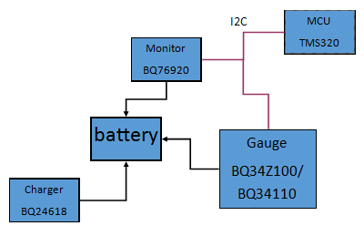
BQ34Z100: a complete battery management system- to verify the connections
↧
DAC37J82: Initialization Set Up
Part Number:DAC37J82
The DAC37J82 is being used with the following Serdes configuration:
LMF = 421, S=1, HD=1, interp = 1. DAC PLL is bypassed.
When following the Initialization steps in section 8.3 in the data sheet, step 12 calls for checking the SERDES PLL lock status. This check returns 0 for both rw0_pll and rw1_pll. Is this expected considering lanes 7:4 are not being used (rw1_pll)?
Are there other things that can be checked at this point to verify that things are in a good state?
↧
↧
LAUNCHXL-CC2650: Error when enabling BLE 4.2 Privacy feature
Part Number:LAUNCHXL-CC2650
Hi,
I am trying to enable BLE4.2 Privacy feature for Random Addressing but when I uncommented DBLE_V42_FEATURES=PRIVACY_1_2_CFG from build_config.opt I am getting the below linking error.

↧
TMS320F28069F: Current feedback circuit in instaspin foc
Part Number:TMS320F28069F
Dear TI Instaspin FOC Team!
Currently I am working with Instaspin FOC on TMS320F28069F.
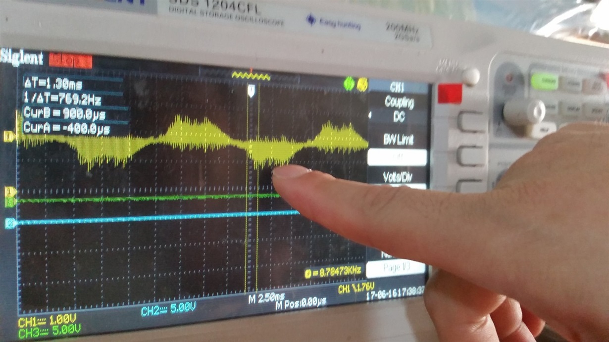
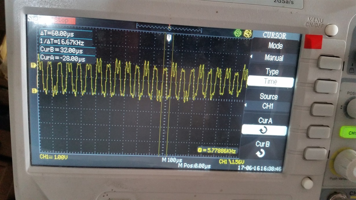
There are several strange issues now, but the most relevant one to those issues , I think is current feedback circuit.
What I really want to know is that, is it necessary to do some smoothing for proper current reading via ADC?
I know on SVM, the ADC catches the current at boundary of SVM period, so that it will be after SVM active period.
Let me attach the waveform here.
↧
TPS92691-Q1: Please help to check my simple design for TPS92691
Part Number:TPS92691-Q1
Dears:
I make the design more simple ,buck-boost topologic,Vin 9~16V,Vout 12~15V ,Iout 1A~1.2A .
Please help to check my schamatic due to I reduce some parts compared with application in datasheet.
↧
↧
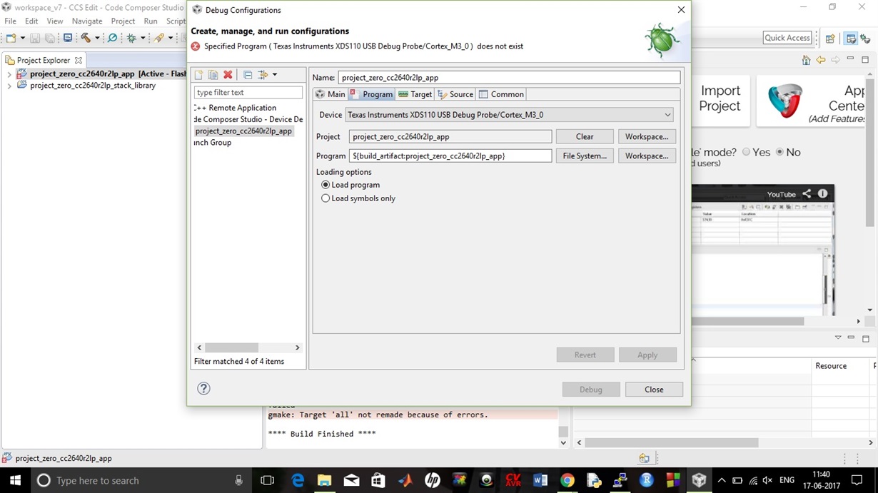
CCS/CC2640R2F: I cannot debug project0 of lab due to the following error in debug config.
↧
CCS/TMS320F28335: Matlab generated code for code composer studio
Part Number:TMS320F28335
Tool/software: Code Composer Studio
Hello all,
I am working on TMS320F28335 microcontroller. I have configured that microcontroller with matalb 2015b . I have made a required simulink model and deployed that model to microcontroller card to get desired output. It is working fine. After deploying the model and build process , matlab has generated a folder with file name_ert_rtw and this file contains some c source file and headers files and some other files. Now, i want to use these files in code composer studio 6 to get desired output without interfacing with matlab.
Can i do this ? Please help me in this. I will be very thank full to you. I have attached that folder, please find the attachment.(Please visit the site to view this file)
↧
TRF7963A: How to read/write Mifare M1 card
Part Number:TRF7963A
Hello,
I am using MSP430G2553+TRF7963A to read/write Mifare M1(S50) card, origin code is sloc251.zip, now read NTAG213 OK,
is there any demo code about S50 card?
I find a package named TRF796X_TRF7970X_MIFARE_12_2013, it seems the right code I need, but not approved yet.
Is there more resource for reference?
Thanks.
Best Regards,
Howrd
↧
cc2530: cc2530
↧
↧
CC3200-LAUNCHXL: External Antenna (UFL Connector)
Part Number:CC3200-LAUNCHXL
I am testing a CC3200 Launchpad XL with an external antenna, and the RSSI that I am measuring is 16 dB worse than the RSSI that I measure with the chip antenna.
The resistor remains same at R111 and i have soldered R110 (0 ohm) also, i have external antenna at J24. Will Wifi signal goes to both external antenna connected at J24 and the chip antenna or wifi signal goes to external antenna connected at J24 and not to the chip antenna??
or let me know it's mandatory to remove R111 and solder only R110 resistor. Do I need to take other steps to switch to the u.fl socket?
I'm noticing the component L8 that is not placed on the board. Does that need to be matched to the antenna I am using?
I've tried several different quarter-wave antennas and dipole antennas, but the results are all significantly worse than when the board is configured for the chip antenna.
↧
CC1350STK: How can I do next that I have finish the setting http://processors.wiki.ti.com/index.php/Cc26xx_sw_examples
Part Number:CC1350STK
Hi,
I have used the BBB setting the development environment from the CC26XX Contiki Examples,
the development environment is ok.
But I have some questions:
1 The web that i can change for myself?If I can change,where is the file path.I can't fine the [bbbb::100] source.
2 How can i do that i can view from the internet?
Best regards,
Selina
↧
audio amplifier bridge problem
I am working on a audio power amplifier . AB class. it is designed to have 2kw power per Channel. I have 2 channel on my PCB board.. my problem is :
when I use each of amplifiers in single mode it works properly , but when i am trying to bridge them i see a clamped voltage in out put voltage .
there is only problem in 1 cycle of 2 cycle of total sin output wave for test the input signal is: sin(t)
thank you all
↧
CCS/DRV8301-69M-KIT: spi connection drv8301-69m and arduino
Part Number:DRV8301-69M-KIT
Tool/software: Code Composer Studio
Hello,
I would like controll the drv8301-69m kit with spi, to start and stop the motor and set the speedref value. I use an Arduino as master and the pins of the Arduino are connected to the J8 of the board (SOMI->SD-I, SIMO->SD-O, GND-GND, CLK->CLK, GPIO->GPIO(SS)). I didn't change the void HAL_setupSpiA(HAL_Handle handle) at the moment.
The problem is i don't getting any value.
In the proj_lab main i added HAL_setupSpiA(halHandle); to init the SPIA.
// variable
uint_least16_t value;
The read function is in the for-loop -> value = SPI_read(spiAHandle);
hal.c:
void HAL_setupSpiA(HAL_Handle handle)
{
HAL_Obj *obj = (HAL_Obj *)handle;
SPI_reset(obj->spiAHandle);
SPI_setClkPolarity(obj->spiAHandle,SPI_ClkPolarity_OutputRisingEdge_InputFallingEdge);
SPI_disableLoopBack(obj->spiAHandle);
SPI_setCharLength(obj->spiAHandle,SPI_CharLength_16_Bits);
SPI_setMode(obj->spiAHandle,SPI_Mode_Slave);
SPI_setClkPhase(obj->spiAHandle,SPI_ClkPhase_Delayed);
SPI_enableTx(obj->spiAHandle);
SPI_enableChannels(obj->spiAHandle);
SPI_enableTxFifoEnh(obj->spiAHandle);
SPI_enableTxFifo(obj->spiAHandle);
SPI_setTxDelay(obj->spiAHandle,0);
SPI_clearTxFifoInt(obj->spiAHandle);
SPI_enableRxFifo(obj->spiAHandle);
//not needed for slave mode SPI_setBaudRate(obj->spiAHandle,(SPI_BaudRate_e)(0x000d));
SPI_setSuspend(obj->spiAHandle,SPI_TxSuspend_free);
SPI_enable(obj->spiAHandle);
return;
} // end of HAL_setupSpiA() function
This is a pic of the register.

Are there any guides or examples to setup the SPI?
Thanks
↧
↧
Handle mqtt reconnect with sdk 1.3.0-
Hi,
Below changes you have to made in MQTT Client example for reconnection in latest sdk 1.3.0-
1. Add a while(1) { start just before the connect_to_broker: label.
+++ while(1) {
connect_to_broker:
while(iCount < iNumBroker)
2. End the while loop just before the end: label.
+++ }
end:
3. Replace the break in the Connect Failure Condition with a continue;
if((sl_ExtLib_MqttClientConnect((void*)local_con_conf[iCount].clt_ctx,
local_con_conf[iCount].is_clean,
local_con_conf[iCount].keep_alive_time) & 0xFF) != 0)
{
UART_PRINT("\n\rBroker connect fail for conn no. %d \n\r",iCount+1);
//delete the context for this connection
sl_ExtLib_MqttClientCtxDelete(local_con_conf[iCount].clt_ctx);
--- break;
+++ continue;
}
4. Replace the break in the Subscribe Failure Condition with a continue;
if(sl_ExtLib_MqttClientSub((void*)local_con_conf[iCount].clt_ctx,
local_con_conf[iCount].topic,
local_con_conf[iCount].qos, TOPIC_COUNT) < 0)
{
UART_PRINT("\n\r Subscription Error for conn no. %d\n\r", iCount+1);
UART_PRINT("Disconnecting from the broker\r\n");
sl_ExtLib_MqttClientDisconnect(local_con_conf[iCount].clt_ctx);
local_con_conf[iCount].is_connected = false;
//delete the context for this connection
sl_ExtLib_MqttClientCtxDelete(local_con_conf[iCount].clt_ctx);
iConnBroker--;
--- break;
+++ continue;
}
5. Replace the goto end: in the disconnect message handler with a break;
if(iConnBroker < 1)
{
//
// device not connected to any broker
//
--- goto end;
+++ break;
}
it working for re connection attempt.
Best Regards,
Shashank
↧
CC1310: What is the Lowest Carrier Frequency for CC1310
Part Number:CC1310
Hi,
I was wondering what is the lowest carrier frequency we can use the cc1310 at? I have a cc1310 launchpad btw.
I see in the data sheet that it supports the 315MHz band. Im assuming it can go a bit lower than that.
This info is not for a commercial product but for me to look at the Tx output in time domain on my oscilloscope (my scope starts struggling a bit above 300MHz. Below that it works fine.)
Thanks.
↧
CCS/TMS570LS0432: TMS570ls04 Launchpad R8 register
Part Number:TMS570LS0432
Tool/software: Code Composer Studio
Hi , I am using TMS570ls04 launchpad for SCI communication. I have reference programme for that but in that programme it is mentioned that you have remove R8 from launchpad for proper readings of UART received data . But I am not getting actually why to remove that register. I am new to this controller . what happened when i removed it and if i kept as it ?
Thank you.
↧
CC2640R2F: Using simplebroadcaster example
Part Number:CC2640R2F
What are the things we can transmit using simplebroadcaster example and how to set the transmitter power.
↧
↧
CCS/TM4C1294NCPDT: Composite device instead of Virtual Comport in TM4C1294NCPDT launchpad in window 8 and window 10
Part Number:TM4C1294NCPDT
Tool/software: Code Composer Studio
Dear All,
I am working on Tiva launchpad having TM4C1294NCPDT micro-controller. I am trying to use USB_DEV_CSERIAL example from tivaware without any change it is running fine but when I am checking for Virtual Comport in Device manager I am getting Composite device instead of Virtual Comport. I am using window 10 and same issue occurred with window 8. But when we are using window 7 we are able to get Virtual Comport .
I am not able to resolve this problem. Please let me know the solution for this.
Thanks & Regards
Parvez Alam
↧
ADS1232: FIR Filer for stable reading from ADC
Part Number:ADS1232
I am using ADS1232 for weigh scale application. Output of loadcell is 2mV/V.
Excitation voltage -- 5V, Samples per second -- 10nos.
Gain = 64
Above parameters are set for ADC. At present I am masking 4 LSB and the result of conversion has fluctuations of @ 200 in raw counts.
I tried moving average algo but still results are not satisfactory.
When I use 5 kg weight which is displayed as 5000; the last digit fluctuates by 2.
Is FIR filter required for additional stability. If yes can you suggest me the parameters for filter.
I am trying for 6 readings(order).
Thanks
S Agashe
↧
CC2640R2F: How to set the RAW data send by the BLE
Part Number:CC2640R2F
I want to customize the raw data sent by the BLE but could not find how to do it.
↧