Quantcast
Channel: Forums - Recent Threads
Viewing all 262198 articles
Browse latest View live

AM4378: About PROFINET /Ethernet/IP Protocol Issue

$
0
0

Part Number: AM4378

Hi Sir 

After referring to below document, we have some questions

About Profinet and Ethernet/IP, according to Industrial Communication Protocols Supported on Sitara™ Processors,

Molex is the software stack supplier and Molex can provide PROFINET Controller Stack, PROFINET Device Stack, Ethernet/IP scanner Stack and  Ethernet/IP adapter Stack.

1. Can PROFINET Controller Stack run in TI Linux RT environment stably or we have to port it by ourselves?

2. Can PROFINET Device Stack run in TI Linux RT environment stably or we have to port it by ourselves?

3. Can PROFINET Controller Stack run in TI RTOS environment stably or we have to port it by ourselves?


4. Can Ethernet/IP scanner Stack run in TI Linux RT environment stably or we have to port it by ourselves?

5. Can Ethernet/IP adapter Stack run in TI Linux RT environment stably or we have to port it by ourselves?

6. Can Ethernet/IP scanner Stack run in TI RTOS environment stably or we have to port it by ourselves?

7. Is the Ethercat master stack free if we use TI RTOS ?

please advise.

BR

Yimin


MSP430F5529: EPD* Extension Kit Generation 2

$
0
0

Part Number: MSP430F5529

Hi Experts,

Recently I started working on EPD* Extension Kit Generation 2 with TI Launchpad MSP430F5529LP But there in User Guide I didn't found any guide to compile the code in IAR. If anyone can help it will be helpful and also be appreciated.There I only saw for Code Composer Studio.

Thanks & Regards,

TPS61021A: EN input current and temperature dependency

$
0
0

Part Number: TPS61021A

Hi,

Could you specify the EN input current at +85°C?

Several nA at room temp is fine, but leakage very often tend to dramatically increase at elevated temperatures.
So it would be good if you could specify this at +85°C.

Kind Regards
CHA

CCS/CCSTUDIO-KEYSTONE: PLL registers read as 0

$
0
0

Part Number: CCSTUDIO-KEYSTONE

Tool/software: Code Composer Studio

Hi,

I am working with 66AK2G12 device. I am trying to check Main PLL configuration by reading follwoing registers:

1. BOOTCFG_MAIN_PLL_CTL0 (addr - 0x02620350)

2. PLLM (addr - 0x02130110)

3. SECCTL (addr - 0x02130108)

I use the default target configuration with evmk2g.gel gel file. The gel file sets up Main PLL.

On connecting to C66 target, gel file output on console is:

C66xx: GEL Output: Starting K2G GP EVM Initialization ..
C66xx: GEL Output: Reading Device Speed from BOOTCFG_EFUSE_BOOTROM
C66xx: GEL Output: DEVICE SPEED[23:16] ---> 1000 MHz
C66xx: GEL Output: ARM SPEED[9:0] ---> 1000 MHz
C66xx: GEL Output: PLL has been configured (24.0 MHz * 250 / 3 / 2 = 1000.0 MHz)
C66xx: GEL Output: ARM PLL has been configured with ref clock 24MHz, -sysclkp_period 41.6666 (24.0 MHz * 250 / 3 / 2 = 1000.0 MHz)
C66xx: GEL Output: Power on all PSC modules and DSP domains...
C66xx: GEL Output: Power on PCIE PSC modules and DSP domains... Done.
C66xx: GEL Output: UART PLL has been configured (24.0 MHz * 128 / 1 / 8 = 384.0 MHz)
C66xx: GEL Output: NSS PLL has been configured (24.0 MHz * 250 / 3 / 2 = 1000.0 MHz)
C66xx: GEL Output: ICSS PLL has been configured (24.0 MHz * 250 / 3 / 10 = 200.0 MHz)
C66xx: GEL Output: DSS PLL has been configured (24.0 MHz * 198 / 12 / 16 = 24.75 MHz)
C66xx: GEL Output: XMC setup complete.
C66xx: GEL Output: DDR3 PLL Setup ...
C66xx: GEL Output: DDR3 PLL Setup complete, DDR3A clock now running at 533MHz.
C66xx: GEL Output: DDR3A initialization complete
C66xx: GEL Output: K2G GP EVM Initialization Complete.

I am expecting following values in registers:

1. PLLM = 0000011111001 = 249

2. PLLD = 000010 = 2

3. CLKOD = 0001 = 1

However, I see these values in Debug -> Register View:

Looks like CCS is able to read BOOTCFG_MAIN_PLL_CTL0 but not PLLM or SECCTL.

I even tried reading them through Expressions, same result:

I then tried using Gel Script function : CORE_PLL_READ_REGISTER_VALUES, and got following output:

C66xx: GEL Output: The value of MAIN_PLL_CTL0_ADDR is 0x7B003002
C66xx: GEL Output: The value of MAIN_PLL_CTL1_ADDR is 0x00000040
C66xx: GEL Output: The value of PLLCTL_ADDR is 0x00000041
C66xx: GEL Output: The value of SECCTL_ADDR is 0x00090000
C66xx: GEL Output: The value of PLLM_ADDR is 0x00000039
C66xx: GEL Output: The value of PLLDIV1_ADDR is 0x00008000
C66xx: GEL Output: The value of PLLDIV2_ADDR is 0x00008000
C66xx: GEL Output: The value of PLLDIV3_ADDR is 0x00008002
C66xx: GEL Output: The value of PLLCMD_ADDR is 0x00000001
C66xx: GEL Output: The value of PLLSTAT_ADDR is 0x00000006
C66xx: GEL Output: The value of PLLDIV4_ADDR is 0x00008004
C66xx: GEL Output: The value of PLLDIV5_ADDR is 0x00008017
C66xx: GEL Output: The value of PLLDIV6_ADDR is 0x00000000
C66xx: GEL Output: The value of PLLDIV7_ADDR is 0x00000000
C66xx: GEL Output: The value of PLLDIV8_ADDR is 0x00000000

I have based an LED toggle on sysclock and am able to achieve correct toggle period using 1GHz as system clock.

Which makes me think that the PLL is actually setup correctly, but CCS is not able to read it.

Can you please confirm if my understanding is correct?

Also can you please explain this discrepancy?

I looked at device xml file and PLL.xml file and couldn't find anything wrong with them.

I am attaching them for your reference.(Please visit the site to view this file)

(Please visit the site to view this file)

TUSB8041: How to debug if USB hub cannot work

$
0
0

Part Number: TUSB8041

Hi team,

My customer is using this device, when he pulled up USB_VBUS pin to high, no USB device can be detected. What may cause such an issue? What kind of software and hardware debug can we use to find the root cause? Thanks. 

Compiler/BQ34110: problem while read the voltage register.

$
0
0

Part Number: BQ34110

Tool/software: TI C/C++ Compiler

Hello,

 I am using BQ34110 battery gauge ic for one of my application using processor in that i2c bus was enabled and i can read the slave address using i2cdetect gpios-i2c@50 this command and it's showing 0x55, but I try to read the 0x08 and 0x09 voltage register value( using i2cget gpios-i2c@50 0x55 0x08 this command) its show like 0xcc and 0x3c but in the input side i had given the 12v supply, i don't know weather its giving current value or not so please help me out of this.

thanks

ADS1299: Using ADS1299 or ADS1291 for local field potential detection

$
0
0

Part Number: ADS1299

Hi,

Recently I'm working on a project about detecting local field potential which is one of the brainwave. Can ADS1299 or ADS1291 detect this kind of wave?

Thank you!

LAUNCHXL-CC3235SF: Questions regarding data format of HTTP client AT commands.

$
0
0

Part Number: LAUNCHXL-CC3235SF

Hello,

I am curious about the data format for HTTP client AT commands with the CC3235SF.  Essentially, I have to do a POST request with JSON.

The first step is to set the header:  AT+HttpSetHeader = [index],[option],[flags],[format],[length],[data]

I am trying to set req_content_type to 'application/json'.  I see in the documentation the format is either binary or Base64.  Knowing this I just converted the string 'application/json' to hex, and sent the command as follows:

AT+HttpSetHeader=0,req_content_type,persistent,0,16,0x6170706c69636174696f6e2f6a736f6e

Is my understanding correct?  I have the same question about HttpSendReq for conducting a POST.

Thank you in advance,

Ben


TPS92612-Q1: Part failure at 24VDC and 7s1p LED-string @ 50mA

$
0
0

Part Number: TPS92612-Q1

Hi,

Short story: 7 LEDs midpower in one string (7s1p), approx. 19V Vf in total. Supply voltage is 24VDC. Design done as per reference board design but with 2.2ohm current setting resistor. When cycling power on/off the device can suddenly self-destruct and go up in smoke. Happens fairly easy, 10-15 power cycles at most. First prototypes built with parts from Mouser. Is this part tested and qualified for 24VDC? We really can't see what we do wrong with this device?

Regards,

Martin

ESDS312: Surge and ESD Protection Diodes for USB 2.0

$
0
0

Part Number: ESDS312

Hi,

The recommended Input voltage range which is mentioned in ESDS312 data sheet is from 0V to 3.6V, so can ESDS312 be used as the surge and esd protection diodes for D+, D- and VBUS on USB 2.0 ?
Additionally, please tell me how to prevent latch-up when IEC 61000-4-2 Contact Discharge is applied continuously at +/- 8kV.
(e.g.: Adding other surge protection diodes)

Best regards,
Kato

TPS61022: TPS61022 maximum Output current support

$
0
0

Part Number: TPS61022

Hi Team,

If we select the TPS61022 then what will be the maximum continuous Output current supported?

In our Application, we would need 4V, 5.5A continuous with it.

Please suggest ASAP.

Thanks

Saumil

TDP142: Request a Design Review & Check a Configuration.

$
0
0

Part Number: TDP142

Hello

I request a design review for TDP142.


and I check a configuration of below

Best Regards.

TPS61177A: TPS61177A power on control Timing

$
0
0

Part Number: TPS61177A

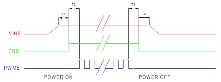
For LCD Module spec request, may I have your suggest for below pic T1~T4 Timing , I can't find it from spec, thanks !

Thanks and Best Regards

James Su

DRV8353RH-EVM: About the dead time.

MSP430F2418: Unable to set P2.3 pin to high.

$
0
0

Part Number: MSP430F2418

Hi,

I am using MSO430F2418 for my project.  I am sending  Hello world message to Bluetooth module via UART pins. Also I need to set pin P2.3 to high to reset the Bluetooth. Unfortunately Im unable to set that perticuler pin to high. When I check the voltage at Reset pin  of Bluetooth it is low.

I am just copying my code here. Can someone look into it and tell me the solution. Thank you.

#include <stdio.h>
#include <msp430.h>				


const char string[] = { "Hello World\r\n" };
unsigned int i;

int main(void){
  WDTCTL = WDTPW + WDTHOLD;                 // Stop WDT

  if (CALBC1_1MHZ==0xFF)                    // If calibration constant erased
  {
    while(1);                               // do not load, trap CPU!!
  }

  DCOCTL = 0;                               // Select lowest DCOx and MODx settings
  BCSCTL1 = CALBC1_1MHZ;                    // Set DCO
  DCOCTL = CALDCO_1MHZ;
   P2DIR|=0x08;
   P2OUT|=0x08;
  P3SEL = 0x30;                             // P3.4,5 = USCI_A0 TXD/RXD
  UCA0CTL1 |= UCSSEL_3;                     // SMCLK
  UCA0BR0 = 8;                              // 1MHz 115200
  UCA0BR1 = 0;                              // 1MHz 115200
  UCA0MCTL = UCBRS2 + UCBRS1;               // Modulation UCBRSx = 5
  UCA0CTL1 &= ~UCSWRST;                     // **Initialize USCI state machine**
 // IE2 |= UCA0RXIE;                          // Enable USCI_A0 RX interrupt
  IE2 |= UCA0TXIE;
  __bis_SR_register(LPM0_bits + GIE);       // Enter LPM0, interrupts enabled
}

#pragma vector=USCIAB0TX_VECTOR
__interrupt void USCI0TX_ISR(void)

{
        UCA0TXBUF = string[i++]; // TX next character
       if (i == sizeof string - 1){ // TX over?
        IE2 &= ~UCA0TXIE; // Disable USCI_A0 TX interrupt
       _delay_cycles(1000000);
        i = 0;
        IE2 |= UCA0TXIE; // Enable USCI_A0 TX interrupt
       }
 }


TMS320F280049: How to disable ADC interrupt when DMA are used

$
0
0

Part Number: TMS320F280049

Hello,

My system is the following:

 1. PWM SOCA interrupt trigger ADC conversion

    // Disable SOCA
    EPWM_disableADCTrigger(EPWM1_BASE, EPWM_SOC_A);

    // Configure the SOC to occur on the first period event
    EPWM_setADCTriggerSource(EPWM1_BASE, EPWM_SOC_A, EPWM_SOC_TBCTR_ZERO);

    // Set prescale to trigger ADC each 20us (2 periods of PWM)
    EPWM_setADCTriggerEventPrescale(EPWM1_BASE, EPWM_SOC_A, 2);

    // Start ePWM1, enabling SOCA
    EPWM_enableADCTrigger(EPWM1_BASE, EPWM_SOC_A);


  // Measure TLoad, pin A1
  ADC_setupSOC(ADCA_BASE, ADC_SOC_NUMBER0,ADC_TRIGGER_EPWM1_SOCA,
               ADC_CH_ADCIN1, 140);
  // Measure IBus, pin A2
  ADC_setupSOC(ADCA_BASE, ADC_SOC_NUMBER1,ADC_TRIGGER_EPWM1_SOCA,
               ADC_CH_ADCIN2, 140);
  // Measure UBus, pin A3
  ADC_setupSOC(ADCA_BASE, ADC_SOC_NUMBER2,ADC_TRIGGER_EPWM1_SOCA,
               ADC_CH_ADCIN3, 140);

  // Measure VLoad is connected to PGA5_IN pin internally connected to A14
  ADC_setupSOC(ADCA_BASE, ADC_SOC_NUMBER3, ADC_TRIGGER_EPWM1_SOCA,
               ADC_CH_ADCIN14, 140);

  // Set SOC3 to set the interrupt 1 flag of ADC A. Enable the interrupt and make
  // sure its flag is cleared.
  ADC_setInterruptSource(ADCA_BASE, ADC_INT_NUMBER1, ADC_SOC_NUMBER3);
  ADC_enableInterrupt(ADCA_BASE, ADC_INT_NUMBER1);
  ADC_clearInterruptOverflowStatus(ADCA_BASE, ADC_INT_NUMBER1);
  ADC_clearInterruptStatus(ADCA_BASE, ADC_INT_NUMBER1);

  // Enable ADC A interrupt 1
  Interrupt_enable(INT_ADCA1);


 2.  At is turn,  interrupt 1 of ADC trigger DMA transfer

  DMA_initController();

  DMA_setEmulationMode(DMA_EMULATION_STOP);

  DMA_configAddresses(DMA_CH1_BASE, (void*)(&adcaRawMeasureSamples[0]), (void*)(&AdcaResultRegs.ADCRESULT0));

  DMA_configBurst(DMA_CH1_BASE, sizeof(ADCA_MEASURE_t), DMA_SRC_BURST_STEP, DMA_DEST_BURST_STEP);

  DMA_configTransfer(DMA_CH1_BASE, NUM_MEASURE_SAMPLE, DMA_CH1_SRC_TRANSFER_STEP, DMA_DEST_TRANSFER_STEP);

  DMA_configMode(DMA_CH1_BASE, DMA_TRIGGER_ADCA1, DMA_CFG_ONESHOT_DISABLE | DMA_CFG_CONTINUOUS_ENABLE | DMA_CFG_SIZE_16BIT);

  DMA_enableTrigger(DMA_CH1_BASE);

  DMA_setInterruptMode(DMA_CH1_BASE, DMA_INT_AT_END);
  DMA_enableInterrupt(DMA_CH1_BASE);

  DMA_disableOverrunInterrupt(DMA_CH1_BASE);

  DMA_clearTriggerFlag(DMA_CH1_BASE);

  Interrupt_enable(INT_DMA_CH1);

  DMA_startChannel(DMA_CH1_BASE);

 3. At the end of DMA transfer ADC result is treated inside DMA channel 1 interrupt

My problem is that my system doesn't works if I don't declare and interrupt function for ADC as following:

Interrupt_register(INT_ADCA1, &adcA1ISR);

static __interrupt void adcA1ISR(void)
{
  // Clear the interrupt flag and issue ACK
  ADC_clearInterruptStatus(ADCA_BASE, ADC_INT_NUMBER1);

  //
  // Check if overflow has occurred
  //
  if(true == ADC_getInterruptOverflowStatus(ADCA_BASE, ADC_INT_NUMBER1))
  {
    ADC_clearInterruptOverflowStatus(ADCA_BASE, ADC_INT_NUMBER1);
    ADC_clearInterruptStatus(ADCA_BASE, ADC_INT_NUMBER1);
  }
  else
  {
    // Nothing to do
  }

  Interrupt_clearACKGroup(INTERRUPT_ACK_GROUP1);
}

So I need help to disable ADC interrupt because for me DMA component is in charge to clear ADC interrupt flag and this interrupt is not needed normaly.

Thanks in advance.

Best regards,

Martial

TPS65262: Can TPS65262 two - way LDO be used in parallel?

$
0
0

Part Number: TPS65262

Hi Sir,

      Can TPS65262 two - way LDO be used in parallel?

What should I pay attention to when using parallel?

AM5746: What is the Power Pins Current, and Voltage when connected to TPS659037

$
0
0

Part Number: AM5746

I would like to know the current and voltage values for power pins 

VDD_MPU
VDD_DSPEVE
VDD_GPU
VDD_IVAHD
VDD_CORE
VDD_RTC
VDD_1V8
VDDA_1V8 (PLLs)
1V8_PHY (USB/SATA)
1V8_PHY (HDMI/PCIe)
VDDA_RTC
VDDSHV5 (RTC I/O)
VDDSHV8 (SDIO)
VDDA_USB3V3
VDD_DDR
DUAL-VOLTAGE RAILS
DDR_REF

when connected to a TPS6590378... PMIC. These can be max values also.

MSP432E401Y: MSP432E401Y CAN1 (CAN0) Init fails after power-up reset or external reset ?

$
0
0

Part Number: MSP432E401Y

Dear support,

I have an application using the CANIP, the Ethernet and some I2C and UART serial ports. As long as the code is being executed from the CCS using the debugger attached (XDS110), everything works as expected. Once I remove the debugger or press and external push-button, the system starts up as before with one exception. The signal on the CANIP is completely messed up. All the other interfaces do work as expected except the CANIP. Without knowing I guess it might have to do something with the clocking network on the chip.

The application is using "simplelink_msp432e4_sdk_3_20_00_10" and "FreeRTOSv10.2.1" in TI-CCS 9.1.... using the TI-Compiler.

The init sequence for the canip peripheral is shown below:

unsigned char bbcInitMSP432CANIP(int iCANIP) {

    UNSIGNED8 ret = 0;

    if( 1 == iCANIP) { // CAN controller CAN1

        /* Enable the clock to the GPIO Port B and wait for it to be ready */
        MAP_SysCtlPeripheralEnable(SYSCTL_PERIPH_GPIOB);

        while(!(MAP_SysCtlPeripheralReady(SYSCTL_PERIPH_GPIOB)))
        {/* wait for peripheral ready */
        }
        
        /* Enable CAN1 */
        MAP_SysCtlPeripheralEnable(SYSCTL_PERIPH_CAN1);

        while(!(MAP_SysCtlPeripheralReady(SYSCTL_PERIPH_CAN1)))
        {/* wait for peripheral ready */
        }        

        /* Configure GPIO Pins for CAN mode */
        MAP_GPIOPinConfigure(GPIO_PB0_CAN1RX);
        MAP_GPIOPinConfigure(GPIO_PB1_CAN1TX);
        MAP_GPIOPinTypeCAN(GPIO_PORTB_BASE, GPIO_PIN_0 | GPIO_PIN_1);

....

As mentioned it always works using the debugger. It never works without it. Is there a way to check if the system clock has been stabilized before proceeding?

br

Markus

TCI6638K2K: AIF2 resynchronization not working in XTCIEVMK2K Rev30 EVM board connected via Mistral BreakOut Card with optical external loop back

$
0
0

Part Number: TCI6638K2K

Hi,

We are trying to port our Keystone I(TCI6618) based AIF2 CPRI codebase to Keystone II(TCI6638K2K) . Made the necessary changes and was able to get optical loop back via SFP+ to work with XTCIEVMK2X Rev 30 EVM connected to Mistral Breakout Card (board version RTM-BOCRT Rev:D). When we tried to remove the CPRI loop back cable and re insert the RM state machine is not re synchronizing and is stuck in un sync state. This was confirmed by reading the RM_LK_STS0[0] Register (offset = 0x50014) which was having a value 0x308. Is there anything else required to be done for CPRI re synchronization in Keystone II? The same code base is re synchronizing in Keystone I and CPRI state machine goes back to sync state (ST3) when the optical loop back cable is re inserted after removal (custom hardware for Keystone I)

regards

Ananth

Viewing all 262198 articles
Browse latest View live


<script src="https://jsc.adskeeper.com/r/s/rssing.com.1596347.js" async> </script>