Quantcast
Channel: Forums - Recent Threads
Viewing all 262198 articles
Browse latest View live

Query related to AD1230 ADC solution

$
0
0

Regarding query related to ADC AD1230, there are certain queries-

Please help to resolve the confusion.


C30 is 1uf non-polar capacitor. Is it sufficient for scale application, as shown in attached circuit diagram ?

Secondly, as you can see in the circuit, We are using filters between load cell & ADC input ? Is it correct ?, Is it really required / Helpful ? please also suggest that is it create problems of  noise , humidity, etc ???


Please help to resolve the issue on urgent basis, attached is the circuit diagram for AD1230.

(Please visit the site to view this file)


Thanks,

Kushanga


8MB SPI flash suport on TM4C1231

$
0
0

Dear Experts

My customer used to use Micron 4MB SPI flash with SC type on TM4C1231.
It works well.
But Micron 8MB SPI flash is SE type.
Can they use SE type SPI flash on TM4C1231?
Or do you have a support list of which 8MB SPI flash is supported on TM4C1231?
Thanks for your comment.

CC2650: core current consumption formulas, (page1: 61uA/MHz) vs (page14: 1.45mA+31uA/MHz)

$
0
0

Hello,

First, please find the titled two numbers 61uA and 31uA.

I think they match @48MHz, but they don't @ lower frequencies.

Can I have your explanation ?

-n

Using USB in OTG mode in TM4C1294NCPDT

$
0
0

Hi,

I am working on tm4c1294ncpdt for my application. Now I am likely to extend my application such that to use USB_OTG in it. I have gone through the example programs in Tivaware. I can find several examples based on USB such as USB_host_keyboard, USB_host_mouse, USB_dev_bulk, USB_dev_serial, etc..

But in my application, I want to use it in an OTG mode and I couldn't find any example program in Tivaware to use USB in OTG mode. So anyone ,please share  your experience with me to use USB in OTG mode. It will be very helpful for me to complete my project.

Thanks in advance.

Regards,

Subash

COUT Capacitor Calculations using LM43601

$
0
0

Hi,

I am designing a 24V to 5V Buck Regulator using LM43601 @ 1A .

 While calculating the Output capacitor value using the formula given in datasheet i got value of around 100uH. But when i use the formula mentioned in TI's "Basic Calculation of Buck power stage" PDF i am getting different value.

Could you please help me in calculating right value for the capacitor. (Please visit the site to view this file)

how to process unused AIN pin of ADS1015

$
0
0

Hi, 

I am trying to use ADS1015 for my design, but i only required to use 3 AIN for ADC process, as ADS1015 have 4 AIN input pin, now my question is how to process that unused AIN pin, just keeping it open or pull down it to GND or pull up to VCC through a weak resistor?

Thank you

Cell Pack Protection

$
0
0

I am assuming 15 series protection IC's like the BQ76940 would still need thermal protection in the pack.  The IC does to take the place of the PTC and the Thermal fuse.

Can Anyone recommend a souce for parts rated for 66 volt parts?

ソフトウェアに関するQA

$
0
0

コミュニティの投稿カテゴリは「アナログ」、「コミュニティ利用方法」、「プロセッサ」、「マイコン」と分かれていますが、Linux,CCS等のソフトウェアに関する質問はできないのでしょうか?


TIDA-00879 ISSUE

$
0
0

HI

I have some doubts on the TI design TIDA-00879. Please help.

Please see the following pictures:

strange behavior of DAC7750

$
0
0

For a sensor device i use 2 DAC7750 in daisy chain together with a CC3200MOD. The first versions of the board use the CLR Signal of DAC7750 to reset the device during power up once.After a redesign i have to use the GPIO pin for other purposes.

After various tests i have the following issue: As i change the digital signals for data, there is a low current on the outputs but the input current mirrors the programmed current in supply. So as i would have a internal current flowing from the outputs to ground. The output current is totaly wrong.

Must the CLR Signal be applied to the circuit ?

Does anybody has an idea for this ?

best regards

Thomas

DRV8432 unused output port shorted to PVDD internally

$
0
0

Hi,

I am currently applying DRV8432 to drive a 3 phase BLDC motor. Thus I am only using half bridge A, B and C and left half bridge D floating at the output.

But recently I found a damage board where PVDD (+48V) and GVDD (+12V) are both shorted to ground (PVDD to ground: 6ohm & GVDD to ground: 8ohm).

After checking, I found out that the shorted was actually originated from DRV8432 output port D.

Output port D is directly shorted to PVDD with almost 0ohm, around 8ohm to ground, and around 2ohm to GVDD.

However, I am not using Output port D to drive any load in my application.

Can you advice what might have cause this kind of damage to port D?

I have set overcurrent protection in latching mode at 5.8A and it never trigger any overcurrent protection before port D is damage.

Looking forward for your reply. Thank you.

MSP432 LAUNCHPAD can't run "msp432p401x_pcm_09"

$
0
0

MSP432 LAUNCHPAD VER 1.0, replaced chip to REV.C;

MSP432WARE: 3.40

Created new project with "msp432p401x_pcm_09", code no changed.

If I didn't add "startup_msp432p401x_ewarm.c" in project, build is OK. When I run under DEBUG session, it will stopped:

And LED (P1.0)on the board did not blink.

If I add  "startup_msp432p401x_ewarm.c" in project, build will failure as:

If I missed anything?

Thanks!

Execute mkfs.ext3 failed on DM8148

$
0
0

Hi,

I am using a DM8148 evm with  linux 2.6.37, I want to format the emmc device but failed.

I am using 4GB emmc.

root@dm814x-evm:~# mkfs.ext3 -j -L "rootfs" /dev/mmcblk1p2
mke2fs 1.41.14 (22-Dec-2010)
Filesystem label=rootfs
OS type: Linux
Block size=4096 (log=2)
Fragment size=4096 (log=2)
Stride=0 blocks, Stripe width=0 blocks
200000 inodes, 800000 blocks
40000 blocks (5.00%) reserved for the super user
First data block=0
Maximum filesystem blocks=822083584
25 block groups
32768 blocks per group, 32768 fragments per group
8000 inodes per group
Superblock backups stored on blocks:
32768, 98304, 163840, 229376, 294912

Writing inode tables: [ 299.710000] Kernel panic - not syncing: Attempted to kill init!
[ 299.710000] Backtrace:
[ 299.710000] [<c0050bf4>] (dump_backtrace+0x0/0x110) from [<c03f3574>] (dump_stack+0x18/0x1c)
[ 299.720000] r7:d6438000 r6:d6438000 r5:d643bee0 r4:c059af90
[ 299.730000] [<c03f355c>] (dump_stack+0x0/0x1c) from [<c03f35d8>] (panic+0x60/0x17c)
[ 299.740000] [<c03f3578>] (panic+0x0/0x17c) from [<c007ac7c>] (do_exit+0x74/0x5e4)
[ 299.750000] r3:c056a05c r2:d643be20 r1:d64380fc r0:c04d292f
[ 299.750000] [<c007ac08>] (do_exit+0x0/0x5e4) from [<c007b270>] (do_group_exit+0x84/0xb4)
[ 299.760000] [<c007b1ec>] (do_group_exit+0x0/0xb4) from [<c0086304>] (get_signal_to_deliver+0x2d4/0x304)
[ 299.770000] r5:d643bee0 r4:0000000b
[ 299.770000] [<c0086030>] (get_signal_to_deliver+0x0/0x304) from [<c004fa78>] (do_notify_resume+0x7c/0x654)
[ 299.780000] [<c004f9fc>] (do_notify_resume+0x0/0x654) from [<c004ce58>] (work_pending+0x24/0x28)

LDC1051 or other Inductance to Digital Converter solution?

$
0
0

Dear Sirs

Is LDC1051 NRND?

Do you recommend other Inductance to Digital Converter solution?

BRS

Nat

[PC(Client) to CC3100(Server) TCP communication] Communication delay is too severe.

$
0
0

Hello. 

I wanted to implement a high-speed communication.

CC3100 is TCP Throughput 13Mhz, UDP Throughput 16Mhz in datasheet.

UDP Throughput is ok.

about 1.6~1.8ms ( Packet size 1442 Bytes).

However, TCP is not.

about 200ms ( Packet size 1452 Bytes )

I do not know why the TCP slow speed.

-lab condition-

STM32F407 + CC3100(Eva)

SPI : 21Mhz (about 20Mhz)

Commu : TCP, UDP Communication

PC : 802.11 B/G/N WiressLan(Usb Type)  / TCP Client Program (Modbus client)

PC(STAtion) <-> CC3100(AP) : Between about 30~50cm

Examples used "SPI_debug_tool", "tcp_socket", "udp_socket", "Getting_started with wlan ap" 

<UDP Wireshark Capture>

sned to data (CC3100 -> PC)

about 1.5~1.8ms

<TCP Wireshark Capture>


Speed is also a problem, but a strange one more point.

269. PSH ACK ( PC->CC3100(Receive) )

270. PSH ACK ( CC3100(Send) -> PC )

271. ACK ( PC -> CC3100(ACK) )

total 210ms 

303. PSH ACK ( PC->CC3100(Receive) )

304. ACK ( CC3100(ACK) -> PC )

305. PSH ACK ( CC3100(Send) -> PC )

306. ACK ( PC -> CC3100(ACK) )

total 200ms

ACK Frame This is not regular.

The same result came out above.

Question.

1. ACK Frame parts that make this one exist in the Stack?

2. ACK Frame or affect the TCP communication speed? 

3. Did ACK Frame is sent from hardware?

4. Method of increasing the speed of the TCP is?  (Can you come up to much?)


TPIC6273 output voltage tolerance scope

$
0
0

Hi Sirs,

Sorry to bother you.

As title. we have use TPIC6273.

We saw there are over/under shoot on waveform.

We would like to know does TPIC6273 have define TPIC6273 output voltage tolerance scope

As i know usually is 5%. Could you help double confirm it??

Many thanks for your help.

MSP432 VcoreとMCLK変更のコード  [msp432info soft]

$
0
0

・ MCLKを高速に設定するときに必要な手続きを、Cプログラミング・コードで説明します。

  事前に Power Control Manager (PCM) で仕様をご確認ください。


・ 内容に誤り、問題、質問が有るときは、PICへご連絡をお願いします。

・ 参照資料  現在(Aug.2.2016

① TRM(Technical Reference Manual) slau356d

② DS(Data-Sheet) slas826e

③ Code Example..\MSP432P401_Code_Examples\CMSIS\msp432p401_cs_03


1 変更箇所


・ PCM:Vcore変更 AM_LDO_VCORE0 --> AM_LDO_VCORE1

・ FCTL:Flash wait states変更:0 --> 1

・ SCDCO変更:DCO=3MHzdefault--> 48MHz -->MCLK


2 Vcore変更


・ VcoreAM_LDO_VCORE0 -> AM_LDO_VCORE1 upします。

・ 変更したあと、PCMreadyになったら、Vcoreが正しく変更されたか確認します。


   /* Step 1: Transition to VCORE Level 1: AM0_LDO --> AM1_LDO */
   PCM->CTL0 = PCM_CTL0_KEY_VAL | PCM_CTL0_AMR_1;
   while ((PCM->CTL1 & PCM_CTL1_PMR_BUSY));
   if ((PCM->CTL0 & PCM_CTL0_CPM_MASK) != PCM_CTL0_CPM_1)     error();

3 Flash wait statesの変更


・ Bank0Bank1wait数を変更します。 wait数はdata-sheetで確認します。

・ note: MCLK=48MHzwait数が、デバイスRevisionで変わります。 code example Rev-Bです。

    Rev-Bデバイス =2   ・・・Preview版 

    Rev-Cデバイス =1   ・・・ 製品版 Aug.01.2016現在


  /* Step 2: Configure Flash wait-state to 2 for both banks 0 & 1 */
   FLCTL->BANK0_RDCTL = FLCTL->BANK0_RDCTL & (~FLCTL_BANK0_RDCTL_WAIT_MASK) | FLCTL_BANK0_RDCTL_WAIT_2;
   FLCTL->BANK1_RDCTL = FLCTL->BANK0_RDCTL & (~FLCTL_BANK1_RDCTL_WAIT_MASK) | FLCTL_BANK1_RDCTL_WAIT_2;

4 DCO変更


・ DC=48MHzに変更して、MCLKに設定します。


   /* Step 3: Configure DCO to 48MHz, ensure MCLK uses DCO as source*/

   CS->KEY = CS_KEY_VAL ;                       // Unlock CS module for register access

   CS->CTL0 = 0;                           // Reset tuning parameters

   CS->CTL0 = CS_CTL0_DCORSEL_5;                   // Set DCO to 48MHz

   /* Select MCLK = DCO, no divider */

   CS->CTL1 = CS->CTL1 & ~(CS_CTL1_SELM_MASK | CS_CTL1_DIVM_MASK) | CS_CTL1_SELM_3;

   CS->KEY = 0;                             // Lock CS module from unintended accesses


5 関係するヘッダー


・ 下記のmsp432p401r.hに、PCM,FCTL,CSの前記右辺で使っているシンボルが定義されています。


AM335x CPSW ports configuration for 1Gbps and 10/100Mbps

$
0
0


I would like to use 2 CPSW ports in AM335x.
Our use case is that one CPSW port as Giga port and other port as 10/100base port.


a) Can I use one CPSW port as rgmii and other port as rmii?


b) 2 CPSW ports configures as rgmii. But one port is as gigabit mode, other port is as 10/100 mode.
Is that supported on AM335x?

Best regards, RY

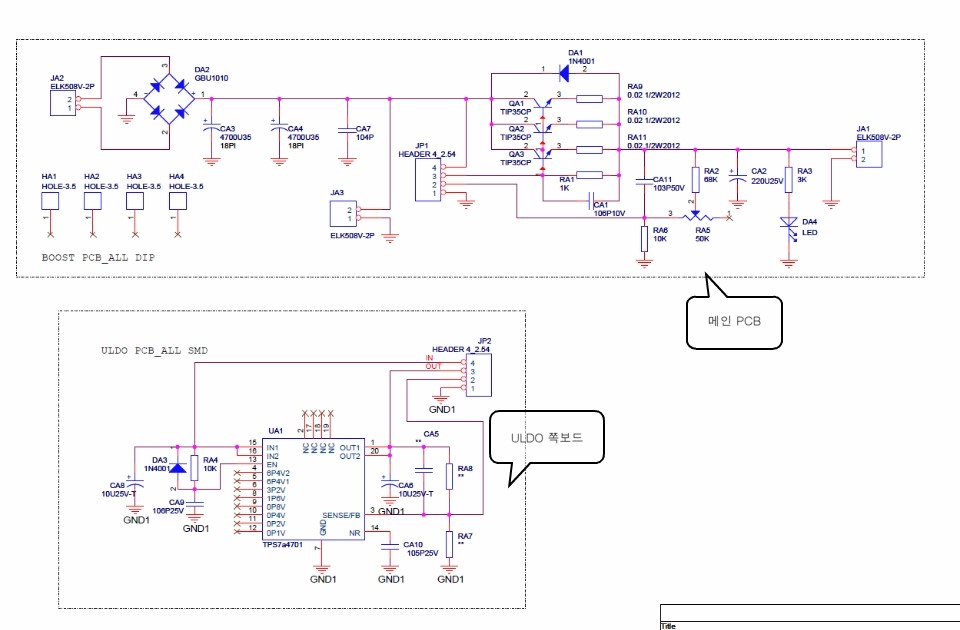
High power linear regulator circuit using TPS7A4701

$
0
0

Dear team,

Would you review the attached this schematic for high power linear regulator using TPS7A4701?

PCA9306 Query

$
0
0

Hi Support,

The PCA9306 recommends connecting EN and VREF2 together with a 200kohm pull up resistor.

Please advise if there are any potential issues if VREF2 is connected directly to a power rail.  Refer to the schematic snapshot below.  

Thanks.

Viewing all 262198 articles
Browse latest View live


<script src="https://jsc.adskeeper.com/r/s/rssing.com.1596347.js" async> </script>