↧
Linux/AM5728: How to enable PCIe with EDMA
↧
LM317A: LM317A_LM317 current limit difference
Part Number:LM317A
Hello
My customer intend to use LM317A, but we have question.
The current limit in the LM317 data sheet is (VIN-VOUT) smaller than 40V,
The current limit in the LM317A data sheet is (VIN-VOUT) equal to 40V.
I think LM317 data sheet is correct ( 15V < VIN-VOUT smaller than :0.4V typ should be correct.
(Its description in LM317A is TYPO)
Is my understanding correct ?
Best Regards
(Please visit the site to view this file)
↧
↧
TLV62150A: TLV62150A enable pin input current
↧
CC3200: Chinese SSID
Part Number:CC3200
Hi Team,
My customer use CC3200 with AIRKISS,now he is facing the following problem:
1.Chinese SSID can not be recognized,and the reason is router uses GBK encoding for SSID, but AIRKISS uses UTF8 encoding instead, which causes the mismatching. My customer tried to conver GBK to UTF via C language,and it takes about 20kb flash, which is too large for his applicaiton.Is there any other mothod to achieve this?
2.Some router can't receive UDP packets when using AIRKISS.
↧
OPA2836: OPA2836IDGS RoHS 3 (2015/863/EU) complaint?
Part Number:OPA2836
Hello Team,
on TI web I can not find if OPA2836IDGS is RoHS 3 (2015/863/EU) conform?
http://www.ti.com/product/OPA2836/pinout-quality
Please can you help?
many thanks Manuel
OP
↧
↧
RTOS/AM5746: PCIe configuration registers
Part Number:AM5746
Tool/software: TI-RTOS
Hi.
My customers have questions on PCIe configuration registers.
Question 1:
About the following registers.
・PCIECTRL_EP_DBICS_PM_CAP [26] D2_SP
・PCIECTRL_EP_DBICS_PM_CAP [25] D1_SP
They looked at Figure 24-163. Do you agree with the following recognition?
Bit = 0 ::: It isn't possible to make state transition in D-state
Bit = 1 ::: It is possible to make state transition in D-state
Question 2:
What is the settings for the following register?
・PCIECTRL_PL_PHY_CTRL_R [31: 0] PHY_CTRL
Question 3:
What happens when you enable the following register?
We can't understand even if I looked at the register Description of TRM.
・PCIECTRL_PL_IATU_REG_CTRL_2[29]INVERT_MODE
Discription:Redefine match criteria as outside the defined range (instead of inside)
Regards,
Rei
↧
CCS/TM4C1294NCPDT: Not able to observe the transmitting data in UART console using SPI Communication
Part Number:TM4C1294NCPDT
Tool/software: Code Composer Studio
Hii,
I am using TM4C1294NCPDT part number and Code Composer Studio.. My Launchpad is acting as Master and as well as Slave also..
Master pin configuration is:
PA2 -------------- SSI0CLK
PA3 ----------- SSI0FSS
PA4 ------------ SSI0XDAT0 // MOSI
PA5 ------------- SSI0XDAT1 // MISO
Slave pin configuration is:
PD3 -------------- SSI0CLK
PD2 ----------- SSI0FSS
PD1 ------------ SSI0XDAT0 // MOSI
PD0 ------------- SSI0XDAT1 // MISO
I am not able to observe the data in UART console but in console it is showing "FAILED"....
Kindly go through the below code.. Is there any new things to add..
(Please visit the site to view this file)
Thanks & Regards,
Venkatadri
↧
CCS/CC2640R2F: The wathdog timeout happens much longer (~120secs) than actual programmed 5 secs value
Part Number:CC2640R2F
Tool/software: Code Composer Studio
We enabled watchdog with 5 secs. At the very first time of flashing the code via JTAG cable is connected, the watchdog timeout happens at 5 secs.
During the time-out RESET happens and JTAG communication with CCS is disabled.
When we remove JTAG and re-start the board with newly flashed binary, the watchdog timeout happens at every 120 secs instead of 5 secs.
What could be reason behind getting 120 secs timeout instead of 5 secs?.
here, is my watchdog code implementation

and below is the WATCHDOG calback function

↧
TS5MP645: How to use TS5MP645
Part Number:TS5MP645
Hi team,
According to below figure, input data is fixed by processor and we can select which Mipi module we use. but our customer wants to realize that input data is selectable and output data is fixed. It is like opposite way. Is it impossible to use such a way? if impossible, do you have any other recommendation devices?
Thanks,
uchihara

↧
↧
MSP430F6638: Clock setting and working of GPIO_setAsPeripheralModuleFunctionInputPin
Part Number:MSP430F6638
1) Please Guide me how can i set clock by using driverlib.
2) I have study the example code but i didn't understand the meaning of GPIO_setAsPeripheralModuleFunctionInputPin. so..
what is the working of GPIO_setAsPeripheralModuleFunctionInputPin function?
thanks
↧
CCS/LAUNCHXL-CC1352R1: OUT of box test with AWR1642 and two pieces of CC1352R1 launch pad.
Part Number:LAUNCHXL-CC1352R1
Tool/software: Code Composer Studio
We have HW environment(AWR1642 , 2 pieces of CC1352R1 LAUNCH PAD[HW rev B, FW:SDK 2.40.1852] ).
we use SDK(simplelink_cc13x2_26x2_sdk_2_40_00_81).
Our goal is people counting sensor information to CC1352R1 sensor node and to collector node. And just packet dump through USB in each node(1642, sensor, collector)
in document TIDUED6(http://www.ti.com/lit/ug/tidued6a/tidued6a.pdf), it recommends us to use simplelink_cc13x2_sdk_2_10_00_48.
Which version should we use with our HW setup? It looks like the latest version simplelink_cc13x2_26x2_sdk_2_40_00_81
If we use simplelink_cc13x2_sdk_2_10_00_48 with CC1352R1 LAUNCH PAD[HW rev B, FW:SDK 2.40.1852] , it does not work.
if we use SDK(simplelink_cc13x2_26x2_sdk_2_40_00_81) with CC1352R1 LAUNCH PAD[HW rev B, FW:SDK 2.40.1852] , it works.
But, it misses patch files for supporting 1642 : 0001-mmwave-cc1352-collector.patch, 0001-mmwave-cc1352-sensor.patch downloaded from
- TIDA-010022 Firmware (Rev. A)
(ZIP, 6614 KB) 29 Mar 2019
Actually when we opened it, it is patch file for IWR6843, not IWR1642 (AWR1642).
Here, we can not proceed testing it "out of box" test with our HW environment
This patch contents looks like "triggering sensor to start sensing". We don't know how to create patch for triggering sensor now.
3.1.2.4 Building the Firmware
The firmware for this TI design is based on the collector and sensor example code provided with the TI
15.4 stack. Patches are included with this TI design to apply the necessary changes to the example code.
Follow these steps to apply the patches and build the example code.
1. Download Simplelink-cc13x2-sdk (version 2.10.00.48) from www.ti.com/.../SIMPLELINKCC13X2-
SDK.
2. Project > Import CCS project.
3. Search in C:\ti\simplelink_cc13x2_sdk_2_10_00_48\examples\rtos\CC1352R1_LAUNCHXL\ti154stack
directory.
4. Import two projects: collector_cc1352r1lp and sensor_cc1352r1lp.
5. Apply the patch for collector node:
a. Right-click collector_cc1352r1lp and go to Team > Apply patch…
b. Apply the collector patch (patch is found in Software Files)
c. Right-click collector_cc1352r1lp and go to Properties
d. In Include Options, add folder ${PROJECT_ROOT}/Application/collector_new
e. In Predefined Symbols, add MMWAVE_SENSOR
6. Apply patch for sensor node:
a. Right-click sensor_cc1352r1lp and go to Team > Apply patch…
b. Apply the sensor patch (patch is found in Software Files)
c. Right-click sensor_cc1352r1lp and go to Properties
d. In Include Options, add folder ${PROJECT_ROOT}/Application/sensor_new
e. In Predefined Symbols, add MMWAVE_SENSOR
↧
DRV8702-Q1: DRV8702-Q1 PWM question
Part Number:DRV8702-Q1
Dear,
About DRV8702-Q1 , is there a standard G-pole and load-driving output waveform for reference?

↧
DS90UB913A-Q1: serializer delay
Part Number:DS90UB913A-Q1
In table 7.10 the serializer delay is defined as 38T or 13T depending on the mode of the chip. The only definition found of T is in table 7.6 as the period of PCLK. If the delay is 38 or 13 times the PCLK then this contradicts figure 10. Can you confirm that the T used in table 7.10 is the clock of the serial FDP link ?
↧
↧
CCS/CC110L: CC110L configuration
Part Number:CC110L
Tool/software: Code Composer Studio
hello i am working on CC110L and sendin and i has tried to configure cc110l . and i has sent two command to CC110L ,follwing are the command which i has sent to cc110l
#define SMARTRF_SETTING_IOCFG0 0x06
#define SMARTRF_SETTING_FIFOTHR 0x47
following i has captured on scope.
ch1..clock signal
ch2. controller-- SI or CC110L SO pin
ch3. controller -- SO or CC110L SI pin

zoom view is below

is this response which is on channel 2 by CC100L is right or wrong??
↧
TMP708-Q1: Material contents
Part Number:TMP708-Q1
Dear TI,
I wants to receive the following materials.
> Material contents
We can not search on the web, so we ask for it.

Look forward to your good news soon.
My email address is below.
> bj.han@wtmec.com
↧
TXB0104: If only give power to VccA and let VccB open (no supply power) will current leak from A side to B side ? and any way to prevent it?
Part Number:TXB0104
Hi
For TXB0104 If only give power to VccA and let VccB open (no supply power) will current leak from A side to B side ? and any way to prevent it?
And how about TXS0104E-Q1 ?
↧
FDC2114: different part number

↧
↧
PROCESSOR-SDK-AM335X: Compilation error
Part Number:PROCESSOR-SDK-AM335X
Hi
I am getting an error while building a code. Please find attached jpg file regarding this.
Regards
Gaurav
↧
Linux/DS90UB941AS-Q1: the 941-948 can transport level (HIGH/LOW) by GPIO3 independently
Part Number:DS90UB941AS-Q1
Tool/software: Linux
my board is imx8qxp,data pata:mipi dsi --> ssd2858-->941-->948-->lcd(1920x720);
in boot up, the gpio3 on 948 sometimes is pull down to 0V while the input GPIO3 to 941 is always 3.3V;
but after there are contents on screen (means display is on,) the gpio3 on 948 is normal to 3.3V;
so,when no dislapy contents input to 941,the 941-948 can transport by GPIO3 independently?  ?
?
↧
TPS73601-EP: TPS73601MDCQREP FB pin is always at 1.6 volts
Part Number:TPS73601-EP
Dear Sir or Madam
The TPS73601MDCQREP at our board is always outputting about 4V, when I measure the pin4(FB), it's about 1.6V .
here is my schematic, Are there anything wrong in my schematic ?I've also tried to changed to feed back resistors to different match groups. But It doesn't work .
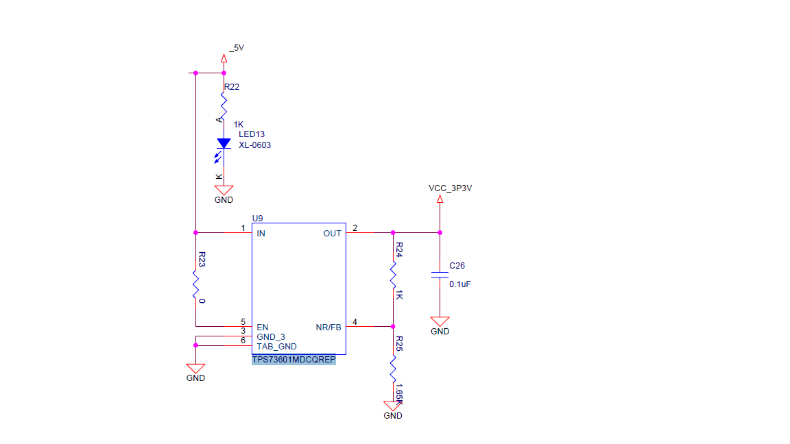
Additionally , There are two places where I can see the formula for calculating the output voltage in the datasheet www.ti.com/.../tps73601-ep.pdf

.


But which one is the wright one ?
best regards.
Anglic
↧