↧
ISO122: Isolation amplifier
↧
DRV8825: DRV8825 absolute current rating
Part Number:DRV8825
HI
i worked with DRV8825 in FULL STEP MODE.
1. In my circuit i designed " i chop" to 3.5A. I saw on every phase 2.5A. Dose the reason is that in full step every phase current is 71% so 3.5A*0.71=2.5A?
2. The absolute current rating is 2.5A continues. In "full step mode" it's means that "I chop" should not pass 3.5A so on every phase would be 2.5A (3.5*0.71=2.5) , or " I chop" should not pass 2.5A so on every phase would be 1.775A (2.5*0.71=1.775).
3. My profile operation is 1.5 SEc ,one time operation, in 4KHz step . The absolute current rating is 2.5A is for continues working. I suppose that 2.5A absolute current rating is for continues working . Is it possible to operate with more current if the operating time is only 1.5 sec one time operation?
4. If so how to calculate how much current could i use?
Thanks
Elyasaf
↧
↧
DRV8353R: DRV8353 damaged twice
Part Number:DRV8353R
Hello.
Several months ago I start to developing bldc motor controller and I select DRV8353RS for driving mosfets. At first it bought a DRV8353RS-EVM for test. I used not heavy motor for it (FL86BLS71). I had a some troubles with auto-tuner but with another attempt I got success. Then after some tests I up supply voltage from 20volt to 40-50 volts and start motor again but it doesn't start and fault led start lighting. Then I start investigate this accident and find that high side mosfet driver of C phase was broken. All of power mosfets stayed healthy. Signals SHC and GHC was short circuit. I had nothing to do and I started do mad experiments. I had suspicions of a suppressor for high side gate and I tried to destroy it by applying voltage between GHC and SHC and to solder one external. Short circuit has gone but looks like suppressor doesn't damaged because at ~15volts something start pass current. Before it I unwire GHC and mosfet gate. After I powered on board and it didn't go to fault. Waveforms at GHC looks good. Then I connected the gate back and it went to fault again. I had no time to wait new parts and I used other half bridge driver for C-phase. Phase A and B and all 3 current shunt still controlled by DRV. It's allowed me to do several tests with motor. After this I made own controller based on DRV8353RS and EVM board. Mosfets, driver and schematic are same. Now I am working at firmware for it. I have some progress of it, torque control work great. But today I damaged DRV again. It happened then I test my code. Motor was spinning and I up supply voltage(from ~20v to ~40v) and it has stopped due to fault. Board start consume more current (now 19mA, was 10mA at 15v and ENABLE = high) and DRV was more hot than early. All mosfets are healthy. I am investigating this accident and now i have next results:
1. It has 250 ohm between GLC and GND, 200 ohm between GLC and VGLD and 420 ohm between VGLD and GND. Looks like low side C driver was damaged.
2. When it powered on. VGLD voltage is around 3 volts.
3. Charge pump has problems too. CPL signal looks like 400khz PWM 3.5 to 0 volts, 50% duty.
4. All other mosfets drivers looks good.
Now I have two damaged DRV8353RS and no idea why it happened and how to fix it. Maybe it due to voltage changing, but I want to use it in similar environment. Have you solution of this problem?
↧
Compiler/CC2642R: SDK 3.10, multi_role_sysconfig project options file
Part Number:CC2642R
Tool/software: TI C/C++ Compiler
Hi,
I am basing on multi_role_sysconfig project from SDK 3.10.
Since the project is using the sysConfig plug-in, there is no more use in the .opt file to configure the options for a build configuration.
But I still would like to define my own app-configurations, which I used to define in those .opt files.
I rather use a file and not define in the "pre-defined symbols" (a file appears on a search in the code, plus, I can add comments).
I saw that the sysConfig generates "ble_app_config.opt", so I traced the use in this file in the .cproject, and tried to add there my build configuration .opt file :
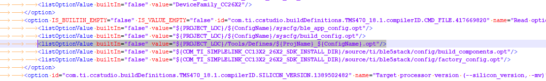
The app compiles successfully but the define is still considered as "not defined" (sections wrapped with "#ifdef ATOM_LOG" still don't compile).
Part of the compilation logs :
Invoking: ARM Compiler
"C:/ti/ccs900/ccs/tools/compiler/ti-cgt-arm_18.12.1.LTS/bin/armcl" --cmd_file="C:/gitClones/multirole_sysconfig_GW-master/multirole_gateway/multirole_app/Debug/syscfg/ble_app_config.opt" --cmd_file="C:/gitClones/multirole_sysconfig_GW-master/multirole_gateway/multirole_app/Debug/syscfg/build_config.opt" --cmd_file="C:/gitClones/multirole_sysconfig_GW-master/multirole_gateway/multirole_app/Tools/Defines/multirole_app_Debug.opt" --cmd_file="C:/ti/simplelink_cc13x2_26x2_sdk_3_10_00_53/source/ti/ble5stack/config/build_components.opt" --cmd_file="C:/ti/simplelink_cc13x2_26x2_sdk_3_10_00_53/source/ti/ble5stack/config/factory_config.opt" -mv7M4 --code_state=16 --float_support=FPv4SPD16 -me -O4 --opt_for_speed=0 --include_path="C:/gitClones/multirole_sysconfig_GW-master/multirole_gateway/multirole_app/submodules/common/inc" --include_path="C:/gitClones/multirole_sysconfig_GW-master/multirole_gateway/multirole_app/submodules/cross_platform" --include_path="C:/gitClones/multirole_sysconfig_GW-master/multirole_gateway/multirole_app" --include_path="C:/gitClones/multirole_sysconfig_GW-master/multirole_gateway/multirole_app/Debug" --include_path="C:/ti/simplelink_cc13x2_26x2_sdk_3_10_00_53/examples/syscfg_preview/rtos/CC26X2R1_LAUNCHXL/ble5stack/multi_role/Application" --include_path="C:/ti/simplelink_cc13x2_26x2_sdk_3_10_00_53/source/ti/ble5stack/controller/cc26xx/inc" --include_path="C:/ti/simplelink_cc13x2_26x2_sdk_3_10_00_53/source/ti/ble5stack/inc" --include_path="C:/ti/simplelink_cc13x2_26x2_sdk_3_10_00_53/source/ti/ble5stack/rom" --include_path="C:/ti/simplelink_cc13x2_26x2_sdk_3_10_00_53/source/ti/ble5stack/common/cc26xx" --include_path="C:/ti/simplelink_cc13x2_26x2_sdk_3_10_00_53/source/ti/ble5stack/icall/inc" --include_path="C:/ti/simplelink_cc13x2_26x2_sdk_3_10_00_53/source/ti/ble5stack/hal/src/target/_common" --include_path="C:/ti/simplelink_cc13x2_26x2_sdk_3_10_00_53/source/ti/ble5stack/hal/src/target/_common/cc26xx" --include_path="C:/ti/simplelink_cc13x2_26x2_sdk_3_10_00_53/source/ti/ble5stack/hal/src/inc" --include_path="C:/ti/simplelink_cc13x2_26x2_sdk_3_10_00_53/source/ti/ble5stack/heapmgr" --include_path="C:/ti/simplelink_cc13x2_26x2_sdk_3_10_00_53/source/ti/ble5stack/profiles/dev_info" --include_path="C:/ti/simplelink_cc13x2_26x2_sdk_3_10_00_53/source/ti/ble5stack/profiles/simple_profile" --include_path="C:/ti/simplelink_cc13x2_26x2_sdk_3_10_00_53/source/ti/ble5stack/icall/src/inc" --include_path="C:/ti/simplelink_cc13x2_26x2_sdk_3_10_00_53/source/ti/ble5stack/osal/src/inc" --include_path="C:/ti/simplelink_cc13x2_26x2_sdk_3_10_00_53/source/ti/ble5stack/services/src/saddr" --include_path="C:/ti/simplelink_cc13x2_26x2_sdk_3_10_00_53/source/ti/ble5stack/services/src/sdata" --include_path="C:/ti/simplelink_cc13x2_26x2_sdk_3_10_00_53/source/ti/ble5stack/services/src/nv" --include_path="C:/ti/simplelink_cc13x2_26x2_sdk_3_10_00_53/source/ti/ble5stack/services/src/nv/cc26xx" --include_path="C:/ti/simplelink_cc13x2_26x2_sdk_3_10_00_53/source/ti/devices/cc13x2_cc26x2" --include_path="C:/ti/simplelink_cc13x2_26x2_sdk_3_10_00_53/source/ti/posix/ccs" --include_path="C:/ti/ccs900/ccs/tools/compiler/ti-cgt-arm_18.12.1.LTS/include" --define=DeviceFamily_CC26X2 -g --c99 --gcc --diag_warning=225 --diag_warning=255 --diag_wrap=off --display_error_number --gen_func_subsections=on --abi=eabi --preproc_with_compile --preproc_dependency="syscfg/smartrf_settings/smartrf_settings.d_raw" --include_path="C:/gitClones/multirole_sysconfig_GW-master/multirole_gateway/multirole_app/Debug/syscfg" --obj_directory="syscfg/smartrf_settings" --cmd_file="configPkg/compiler.opt" "syscfg/smartrf_settings/smartrf_settings.c"
Finished building: "syscfg/smartrf_settings/smartrf_settings.c"
I'd appreciate your help with adding my own custom configuration file.
Thank you,
Amit
↧
IWR6843ISK: Reading TLV from UART stream
Part Number:IWR6843ISK
Dear Community,
I have been trying to find the TLV data format structure provided by the User Guide in the 68xx - People Counting Demo. I am currently using python scripts on a Raspberry Pi as the microcontroller and have been successful in sending the configuration file to the /dev/ttyACM0 port. I am also getting a stream of data back from the /dev/ttyACM1 port.
The stream of data seems to be valid as the data volume increases whenever there are motions detected. However, within the stream I failed to find the hex pattern that indicates the frame header or the TLV header
frameHeaderStructType = struct(... 'sync', {'uint64', 8}, ... % syncPattern in hex is: '02 01 04 03 06 05 08 07'
% TLV Type: 06 = Point cloud, 07 = Target object list, 08 = Target index tlvHeaderStruct = struct(... 'type', {'uint32', 4}, ... % TLV object
This is the code snippet that I am currently using:
ser = serial.Serial("/dev/ttyACM1", 115200)
while True:
received_data = ser.readline()
sys.stdout.write(received_data.encode("hex"))
↧
↧
TSW14DL3200EVM: ADC12DL3200 READ_REGISTERS_FAILED with customer-generated FPGA bit file.
Part Number:TSW14DL3200EVM
We are using the TSW14DL3200 to interface with the ADC12DL3200.
We intend to modify the design loaded into the FPGA - for our purposes.
When loading the FPGA bit file supplied by TI - the "High-speed data-converter Pro v5.00" functions properly.
We created an FPGA bit file using the sources supplied by TI.
Now the "High-speed data-converter Pro v5.00" displays a message: "READ_REGISTERS_FAILED".
We did not change anything on the board - just replaced bit files.
Please advise.
↧
AWR1642: MMWAVE-SDK v03.01.01.02 does not contain xwr16xx folder for mmw demo.
Part Number:AWR1642
Hello expert
I installed mmwave_sdk_03_01_01_02.
mmwave sdk usderguide describes that building mmw demo should be done below folder location.
cd %MMWAVE_SDK_INSTALL_PATH%/ti/demo/<device type>/mmw
There are xwr18xx and xwr68xx but no xwr16xx folder.
What folder should I use for building mmw demo of AWR16xx device?
Thank you.
Lucy
↧
CCS/TMS320F28335: Lost Debug "Flash Settings" when building on a different machine
Part Number:TMS320F28335
Tool/software: Code Composer Studio
I am having an issue making my project portable with respect to the "Debug Flash Settings".
On my machine I have set the Flash settings "Erase Sector Selection" to include Sectors B to G. This leaves the other sectors (A,H) for the bootloader and configuration data.
When I setup a new development environment for another developer, the new setup is erasing all sectors for the same debug option.
The git repo includes the contents of the ".launches" directory.
I have followed the notes in "Debug Configurations" in http://software-dl.ti.com/ccs/esd/documents/ccs_portable-projects.html
However in the new environment, when I look in my "Production Application.launch" file I see my original settings with the correct flash configuration
<stringAttribute key="com.ti.ccstudio.debug.debugModel.ATTR_DEBUGGER_PROPERTIES./home/firmware/original/tms320f28335-master/targetConfigs/TMS320F28335.ccxml.Texas Instruments XDS100v2 USB Emulator/C28xx" value="<?xml version="1.0" encoding="UTF-8" standalone="no" ?> <PropertyValues> <property id="ConnectOnStartup"> <curValue>1</curValue> </property> <property id="EnableInstalledBreakpoint"> <curValue>1</curValue> </property> <property id="IgnoreSoftLaunchFailures"> <curValue>0</curValue> </property> <property id="FlashSectorA"> <curValue>0</curValue> </property> <property id="FlashSectorB"> <curValue>1</curValue> </property> <property id="FlashSectorC"> <curValue>1</curValue> </property> <property id="FlashSectorD"> <curValue>1</curValue> </property> <property id="FlashSectorE"> <curValue>1</curValue> </property> <property id="FlashSectorF"> <curValue>1</curValue> </property> <property id="FlashSectorG"> <curValue>1</curValue> </property> <property id="FlashSectorH"> <curValue>0</curValue> </property> </PropertyValues> "/>
followed by a new line that does not contain any explicit flash settings
<stringAttribute key="com.ti.ccstudio.debug.debugModel.ATTR_DEBUGGER_PROPERTIES./home/firmware/new-environment/tms320f28335-master/targetConfigs/TMS320F28335.ccxml.Texas Instruments XDS100v2 USB Emulator/C28xx" value="<?xml version="1.0" encoding="UTF-8" standalone="no" ?> <PropertyValues> <property id="ConnectOnStartup"> <curValue>1</curValue> </property> <property id="EnableInstalledBreakpoint"> <curValue>1</curValue> </property> <property id="IgnoreSoftLaunchFailures"> <curValue>0</curValue> </property> </PropertyValues> "/>
I have attempted to make the settings in targetConfigs/TMS320F28335.ccxml have the correct flash settings, but these do not seem to persist.
The absolute reference to the location of the ccxml file is surprising since I "Converted" to the linked resource of PROJECT_LOC/targetConfigs/TMS320F28335.ccxml.
It looks like when the Debug option is launched in the new environment:
1. it cannot find the ccxml file at the absolute path
2. It creates a new entry in the launch file for the known ccxml, and uses the default erase sector settings of A to H.
Is there a way to make these erase flash sector settings project portable?
Thanks
↧
BQ76PL455A-Q1: Series communication between two Bq76pl455a-Q1 chips on the same board
Part Number:BQ76PL455A-Q1

Dears:
There are some troubles about series communication between two Bq76pl455a-Q1 chips on the same board.According to the manual about BQ76PL455AQ1,I made the following configuration about series communication.But the expected result did not appear, I am also not sure if there is an communication between the two chips.Please help me to check the configuration,and if it is incorrect please show me how to insolve this problem,ecpecte your response,thanks!
Best Regards!
xiaoming GENG
const uint8_t PWRCONFIG[5]={0xf1,0x0f,0x80,0x55,0xa3};
/*configu for auto-address*/
//const uint8_t COMCONFIG[6]={0xf2,0x10,0x00,0xe0,0x32,0xf5};//Communication Configuration for auto_address125k
const uint8_t COMCONFIG[6]={0xf2,0x10,0x10,0xe0,0x3f,0x35};//Communication Configuration for auto_address250k
const uint8_t ADDR_SEL[5]={0xf1,0x0e,0x10,0x54,0x5f};// auto addressing to select address
const uint8_t AUTO_ADDRESS[5]={0xf1,0x0c,0x08,0x55,0x35};//auto_address mode
const uint8_t CONFIGADDR00[5]={0xf1,0x0a,0x00,0x57,0x53};//confige device 1 to address 0
const uint8_t CONFIGADDR01[5]={0xf1,0x0a,0x01,0x96,0x93};//confige device 2 to address 1
const uint8_t ReadAddress00[6]={0x81,0x00,0x0a,0x00,0x2e,0x9c};//read device 1 address
//const uint8_t ReadAddress00[6]={0x00,0x00,0x00,0x00,0x00,0x00};
const uint8_t ReadAddress01[6]={0x81,0x01,0x0a,0x00,0x7f,0x5c};//read device 1 address
const uint8_t HighSideCommDisable[7]={0x92,0x01,0x10,0x10,0x20,0xb5,0xfc};//disable high-side receiver on differential interface on top of stack
const uint8_t LowSideCommDisable[7]={0x92,0x00,0x10,0x10,0xc0,0xb5,0x88};//disable low-side trasmitter on differential interface on bottom of stack
/*CLEAR ALL FAULT*/
const uint8_t CLEAR_FALUT_SUM01[7]={0x92, 0x01, 0x52, 0xFF,0xC0, 0x58,0x50};//clear device01 fault,start at top
const uint8_t CLEAR_FALUT_SUM00[7]={0x92, 0x00, 0x52, 0xFF,0xC0, 0x59,0xAC};//clear device00 fault
/*broadcast configuration for AFE*/
const uint8_t SMPL_SLY1[5]={0xf1,0x3d,0x00,0x41,0x63};//initial sampling delay :no delay
const uint8_t Cell_CSPER[5]={0xf1,0x3e,0xbb,0x01,0xe0};//first voltage and internal sampling period :60us
const uint8_t AUX_SPER[8]={0xf4,0x3f,0xbb,0xbb,0xbb,0xbb,0x67,0x33};// first tempe sample period:60us
const uint8_t OVERSMPL[5]={0xf1,0x07,0x7b,0x13,0xe0};//oversampling rate 12.6us
const uint8_t NCHAN[5]={0xf1,0x0d,0x10,0x54,0xaf}; //16 cells
const uint8_t CHANNELS[8]={0xf4,0x03,0xff,0xff,0xff,0x00,0x10,0xa0};//all cell and AUX and both internal tempe channels
↧
↧
TSW14DL3200EVM: ADC12DL3200 READ_REGISTERS_FAILED with customer-generated FPGA bit file.
Part Number:TSW14DL3200EVM
Hello,
In continuation of my previous post:
The ADC12DL3200 has an SPI port to interface with the control registers that are part of its logic.
The reference design supplied by TI for the FPGA that is part of the TSW14DL3200EVM board - does not contain any SPI-connection towards the ADC.
This can explain why we get the message "READ_REGISTERS_FAILED" when trying to work with the ADC software and use our FPGA version on the EVM.
Question to TI:
Please provide us the reference design for the TSW14DL3200EVM FPGA - with the SPI part included.
Regards,
Itsik Sela
↧
TPS65987D: GPIO setting in Application Customization Tool

↧
CCS/MSP432P4011: I2C DRIVERLIB - READ/WRITE BIT QUESTION
Part Number:MSP432P4011
Tool/software: Code Composer Studio
Hello everybody,
I'm using the DriverLib documentation to interface an IMU9255 with MSP432, but I don't know how I can send a "read/write" bit using the DriverLib functions. Figure 1 shows a print of all send functions in DriverLib, but neither of them has a "read/write" input. Figure 2 shows the i2c sending sequence, and it needs a "read/write" bit.
Could you guys know how I can find a solution for this?

FIGURE 1.

FIGURE 2.
↧
CCS/TMS570LS3137: Use Gui Composer with custom webserver
Part Number:TMS570LS3137
Tool/software: Code Composer Studio
Hi
It seems very interesting ccs gui composer v2.
I would be interested to use stream target connection via ethernet. I would design css, js widget and html pages with gui composer and bind variables to exchange with monitor on target.
I understood that this is only possibile with a ti webserver, with an internet Connection on both host and target.
We need to use a proprietary webserver on local network, in a closed network, using a direct Connection with target and host.
Is there a way to di this job with powerful instruments in ccs gui composer?
Thank you
↧
↧
BQ40Z60: BQ40z60 DSG FET is not turning on, voltage present in idle state on HIDRV pin
Part Number:BQ40Z60
Hello All,
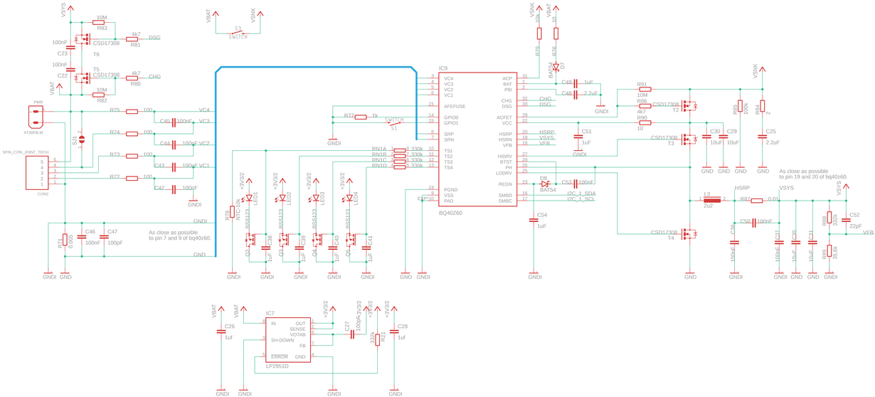
I'm designing custom board with BQ40Z60 and have issue witch DSG FET. When I press change state of this FET, after few ms it is switching off, coil L3 is making noise.
Here is voltage output of DSG gate:

What I am also seeing is, on the VSYS path is always voltage ~2.8V. It is occurring because HIDRV output is constantly providing voltage ~2.8V. When I'm trying to change state of DSG FET here is what is going on on HIDRV output:

May it be the issue why I can not turn on DSG FET? If so, why it is always voltage on HIDRV pin?
.

(Please visit the site to view this file)
↧
ADC12DJ3200: About TIDA-01028
Part Number:ADC12DJ3200
Hi,
I am planning to design a 20GSPS high speed osciloscope using 4 interleaving ADC12DJ3200. In TIDA-01028 user guide,Figures 31 and 32 show the ADC performance with IL spur and without IL spur.I hope to achieve the performance of Figure 32.Here I have two questions:
(1) what calibration has been performed to remove the IL spur?
(2) Does calibration need to be done only once, or do it need to be calibrated every power on cycles?
Thanks a lot!
↧
LMZM23600: step up and step down in one component
Part Number:LMZM23600
Hi
i have a system that the input voltage can be between 20-2V and I need to convert it to 2-6V.
the thing is that sometime the input is 2V and I need to convert it to 6V and sometimes the input is 20V and i need to convert it to 2V so the ranges are pretty big.
I need a component that can be a step up when needed and also a step down when needed and the output voltage should be adjustable between 2-6V.
is there such a component?
thanks in advanced.
↧
OPA846: Relation between GBP as appears in the datasheet to the Gain/freq graph and general BW estimation
Part Number:OPA846
Hi
The datasheet of the device claism 1.75GHz GBP and 400 MHz BW with G = +10 (front page of the datasheet)
The common rule for maximum achivable BW yields: BW = GBP/G = 175 MHz for G = 10
How does that fits the claim of 400 MHz @ G = 10 ?
Also, the gain/freq graph on page 7 (Open-looop gain vs frequency) suggests that at gain = 10 (20dB) we obtain approx 170 MHz BW
What do I miss ?
The amplifier is also calimed to be stable at G > 7 which means it is de-compensated (having two poles before reaching 0dB). Is this fact relates to the confusion I described above ?
I'll appreciate if you can elaborate on that, how to see this is the proper perspective. If there is indeed a relation to the fact of being de-compensated, please elaborate how to properly understand datasheet facts and have them match each other and be able to estimate properly the prospected BW of this kind of amplifier at given gain
Regards, Alex
↧
↧
MSP430FR2433: Possible DriverLib bug in I2C set data rate
Part Number:MSP430FR2433
In DriverLib eusci_b_i2c.c in function EUSCI_B_I2C_initMaster() this code seems in error and doesn't seem to match the comment.
/*
* Compute the clock divider that achieves the fastest speed less than or
* equal to the desired speed. The numerator is biased to favor a larger
* clock divider so that the resulting clock is always less than or equal
* to the desired clock, never greater.
*/
preScalarValue = (uint16_t)(param->i2cClk / param->dataRate);
HWREG16(baseAddress + OFS_UCBxBRW) = preScalarValue;
The division is unsigned and fraction is truncated. Thus the preScalarValue (the clock divider) is smaller and the actual data rate (frequency) greater than desired.
For example for param->i2cClk of 1M and param->dataRate of 400k (the max I2C data rate), preScalarValue is 2 (2.5 with fraction truncated).
Thus the actual data rate will be 500kbps, which is FASTER than desired.
I don't see any code that "biased" the numerator.
CCS 8.02 and a fairly recent version of MSPWare DriverLib
↧
DP83867E: 125MHz SGMII clock generation
Part Number:DP83867E
I am using DP83867 ethernet PHY in SGMII mode.
- On page 6 pin functions it is mentioned that SGMII_COP/CON clock signal will generate continuous 625MHz clock.
- On page 56 of the datasheet PHYCR register has SGMII enable (bit 11) and 125MHz speed enable (bit 4).
I wanted to generate 125MHz from the differential clock from pins SGMII_COP/CON. Which one of the statements is correct?
↧
TPS65987D: TIDA-01627 Altium Schematic and Layout TPS65987D
Part Number:TPS65987D
Hello TI,
How can I have access to the Altium schematic and layout file for this? It will accelerate my design ...
Jay.
↧