Hi,
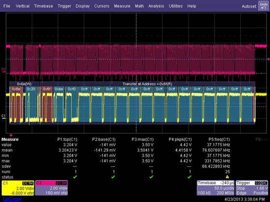
We are seeing this on Channel Readings Register: 0xbe, 0xf0, 0xff, 0xff, 0xff, 0xff, 0xff, 0xff, 0xff, 0xff, 0xff, 0xff, 0xff, 0xff, 0xff, 0xff, 0xff, 0xff.
Registers setting to initialize before reading the Channel Readings Register:
// wait until it is ready.
while ((registerRead(BUSY_STATUS) & ADC_BUSY_STATUS_NOT_READY) == ADC_BUSY_STATUS_NOT_READY)
;
// program Advance Configuration Register(ACR) choose Mode 1
registerWrite(ADVANCE_CONFIGURATION, ADC_ACR_MODE1);
// program Conversion Rate Register
registerWrite(CONVERSION_RATE, ADC_CRR_CONTINUOUS);
// program to Channel Disable Register channel if needed. By default, all channel is enabled.
// program Interrupt Mask Register to choose to mask or not to mask the interrupt status.
registerWrite(INTERRUPT_MASK, ADC_INT_MASK_ALL);
// Program Limit Registers
// Set "START" bit of Configuration Register.
// If needed, set "INT_Enable" bit to 1 to enable the INT pin output.
// Clear the "INT_Clear" bit to enable Round-robin monitoring loop.
registerWrite(CONFIGURATION, (ADC_CR_START|ADC_CR_INT_ENABLE));
Before reading the Channel Readings Register, we wait for the Busy bit to be cleared before reading the Channel Readings Register.
So, current situation is the ADC is communicating via I2C but is not able to get correct digital output (aside channel1) compared to the voltages applied to the ADC.
The schematic for how ADC128D818 is wired is attached. Current registers setting is shown above.
About 1.9V is applied to Channel1 through Channel4, and remaining channel no-connect.
The result we are getting is: 0xbe, 0xf0, 0xff, 0xff, 0xff, 0xff, 0xff, 0xff, 0xff, 0xff, 0xff, 0xff, 0xff, 0xff, 0xff, 0xff, 0xff, 0xff
Please advise:
- What is the correct register settings for using mode1 and continuous polling of voltage at sense pin?
- What we have is shown in the email below. Any change required?
- We are only seeing reading on channel1. Refer to attached scope plot.
- What binary number should be used for setting a 2V high limit for channel1, assume using internal voltage reference?
- ADC reading register (0X20h to 0X27h) channel is 12bit data and limit register (0X2Ah to 0X39h) is 8bit.
- Should I reuse the equation on 14 and replace the power of 12 to power of 8?
Appreciate your prompt reply.
Thanks.
-Koay

