Quantcast
Channel: Forums - Recent Threads
Viewing all 262198 articles
Browse latest View live

TPS56C215EVM-762: there is an audible noise by TPS56C215EVM at 5V to 3.3V application

$
0
0

Part Number:TPS56C215EVM-762

Hi TI expert,

I am Morris who is TI technician. I meet a technical problme on TPS56C215 EVM.  

I based on customer's request to modfy TPS56c215 EVM, the following is the bom list.

L=0.47uH, output cap.=22uF*10, Cff=200pF, RM_L=20kohm, RM_H=160Kohm

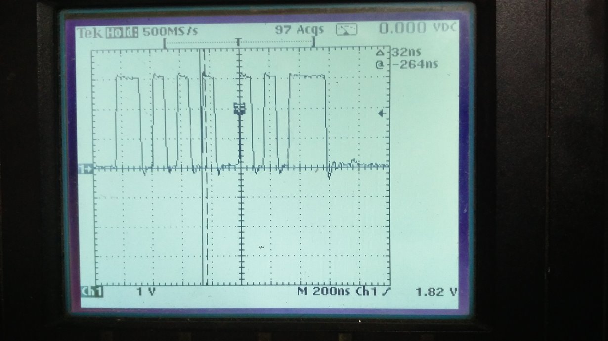
When I did transient test by below condition that has audible noise and transient performance was very bad. 400mVpp. Please refer the attached file.

Vin = 5V, Vout = 3.3V, Freq = 800KHz,

transient condition

0.9A - 9A  slew rate is 2.5A/us, high = 0.5s, low = 0.5s


After I changed Vin from 5V to 12V and keep Vout was 3.3V, the audible noise was gone and transient performance become good (about 168mVpp). Please refer the attached file.  

Question :

1. Is any duty cycle limitation for TPS56C215?

2. Why higher duty cycle will impact transient performance and cause audible noise.

3. If my customer still want to use 5V to 3.3V applicaion, how to solve this problme? I have tried below metholds, but still can't solve it.  

a.I changed freq from 400KHz to 1.2MHz all can't solve it

b.I also try different inductance 0.47uF and 1uF both can't sovle it.

c.I have added output caps from 88uF to 220uF all can't sovle it.  


MSP-EXP430FR6989: PWM on the EXP6989 board

$
0
0

Part Number:MSP-EXP430FR6989

HEllo,

I'm trying to get a PWM out on P2.2 using Timer B. The timer won't start counting: Am I setting this up right?

void PWMsetup(void)

{
// Configure GPIO
P2DIR |= BIT2; // P2.2 as PWM output
P2SEL0 |= BIT2; //Select secondary module function


// Disable the GPIO power-on default high-impedance mode to activate
// previously configured port settings
PM5CTL0 &= ~LOCKLPM5;

TB0CCR0 = 1000-1; // PWM Period
TB0CCTL0 = OUTMOD_7; // CCR1 reset/set
TB0CCR1 = 500; // CCR1 PWM duty cycle
TB0CTL= TBSSEL__ACLK | MC__UP | TBCLR;  // ACLK, up mode, clear TBR

}

AMC1200: Adding the model to Orcad PSPICE

$
0
0

Part Number:AMC1200

hi,

I tried to change the AMC1200.txt to AMC1200.lib and tried to add into Orcad PSPICE. Unfortunately it shows an error.

Could you please help me to add the same into PSPICE model library

Thanks & regards,

Rajasekaran

CC3120: sl_WLanGetNetworkList doesnt Return All APs

$
0
0

Part Number:CC3120

Hello,

We have our custom board with CC3120 and noticed that sl_WLanGetNetworkList it doesn't return all APs. Tried setting device to default mode as explained in https://e2e.ti.com/support/wireless-connectivity/wifi/f/968/t/694250?CC3120-sl-WLanGetNetworkList-Doesnt-Return-All-APs.

Tried to connect to an AP which is not returned in the scan and I got SL_ERROR_WLAN_INVALID_ROLE.

sl_DeviceGet() returns:

CHIP 822083584
MAC 31.2.0.0.0
PHY 2.2.0.6
NWP 3.7.0.1
ROM 0
HOST 2.0.1.22

The same code and service pack works (returns all APs) on CC3120BOOST.

Crystals on the board:

Fast clock: ABM10W-40.0000MHZ-4-K1Z, +/-10ppm, connected with 6pF capacitors.

Slow clock: ABS07-32.768KHZ-9-T, +/-20ppm, connected with 12pF capacitors.

Can you please advice on what else could I try to debug this?

Thank you,

Calin

UCC2897A: Feedback Loop Compensation

$
0
0

Part Number:UCC2897A

Dear Gents,

Looking at reference documents SLUA535 (section 6, Compensating the feedback loop) and SLUA702, I spotted notable differences in modelling of the active clamp circuit:

In SLUA535, it is stated that double pole at frequency (1-D)*fres (where fres is Lm with Cclamp resonance) occurs. On the contrary, in SLUA702 comprehensive analysis is done proving that there is a double zero at the aforementioned frequency and a double pole at slightly lower frequency. Can you please advise which one is true or why are the results different ?

In addition to that, I'd like to ask whether the same frequency response characteristics (poles, zeroes implied by the active clamp circuit) apply to voltage mode control (e.g. LM2025A) or is there any difference ?

Best regards,

Robert

AWR1642BOOST: Where is the thermal sensor location for calculating SNR?

$
0
0

Part Number:AWR1642BOOST

Dear support team

  The following figure shows the equation of SNR and maximum distance from AWR1642 document. 

Could you tell me how to get the T(Antenna temperature) from the AWR1642BOOST?

If T(Antenna temperature) can be got from the temperature sensor, where is the location of this sensor?  Is it on board or in the AWR1642 Single-Chip?

Best Regards,

Roger

TMS320F28375S: TMS320F28375S USB transient noise

$
0
0

Part Number:TMS320F28375S

Respected sir,

                  I am using USB in my motor control application. The USB works fine till i start the switching of IGBT in POWER section. The transient noise gets added on the D+ and D- lines. So what are the options to remove this noise??    My D+ and D- lines are directly going to the USB connector from controller. I have not used any component in between. I am attaching the snap of noise free and noisy signal.

Regards,

Digvijay

TLC5943: GS Data Greater than 0300h

$
0
0

Part Number:TLC5943

Team,

After erasing the micro-controller driving the TLC5943 LED driver and having a pull-up on the BLANK input signal, some of the output channels are still ON. Looking on the data sheet: Does need GS data to be greater than 0300h? This is not mentioned on the BLANK paragraph:

Thank you.


TUSB2046B: TUSB4026B cannot connecte

$
0
0

Part Number:TUSB2046B

 When two devices are connected at the same time, there is a probabilistic identification of the device. If the other device is removed, it can be recognized normally. At present, three roads are used. If the second road and the third road are simultaneously mounted, the third road will have a high probability of not identifying the equipment. Remove the second device, the third channel can be recognized normally. The plug-in module is a full-speed HID device

pls help check it and review the SCH and give some suggestions how to debug it, tks!

OPA211: Alternative for LT1128CS8

$
0
0

Part Number:OPA211

Hi,

could you recommend an alternative to the LT1128CS8?

I dont have more details to this point of time unfortunately, but I hope with a Voltage Noise of 1.1nV/√Hz Max at 1kHz the selection should be limited already,

Thanks
Fred

ADS124S06: DOUT/DRDY function

$
0
0

Part Number:ADS124S06

Dear Team,

How can we use DOUT/DRDY dual function pin for both MISO and DRDY functions.

When CS pin is high and ADC is in Continuous conversion mode at 5sps low latency  we observed that MISO/DRDY pin showing continuously High on CRO.

Please let us know the correct wave form of above condition.

Regards

Surya

DLP6500FYE: DLP6500 EVM Trigger pinout

$
0
0

Part Number:DLP6500FYE

Hi can someone supply we with a pin out for the trigger connectors on the DLP6500 EVM board?  

Thanks for your time!

-Alex

SN65LVCP204: Can SN65LVCP204 be used between DS92LV2421 and DS92LV2422?

TLV320AIC3104: Codec output high for 0 volts in

$
0
0

Part Number:TLV320AIC3104

Hi,

I am using a 320AIC3104 codec using LINE2 as the only input to the left PGA, the PGA gain is 0 db. The digital values are then fed to RIGHT_LOP, again gain at 0db.

When I put 0 volts as the input the RIGHT_LOP output shows the common mode voltage as set by register 40.

I would have expected 0 volts in to give 0 volts out. The input high pass filters are disabled.

If I change the PGA gain to, say, -6 db then the values read from the codec go down, at 0 db they are in the 0xF800 range.

Regards,

TMS320F28027: Simple way to use watchdog on Piccolo?

$
0
0

Part Number:TMS320F28027

I've taken a look at TI's example program for using the watchdog timer.

It seems easy enough but I have a basic question:  where is the timer duration set?  I noticed a function, namely WDOG_clearCounter() that clears its current count but I don't see any API function to set the length of time or number of count-ups before the watchdog resets.

In the example code, the API function WDOG_setCount() is not called, so what's the default time before the watchdog will reset?  The API library documentation only supplies the function name and its parameters, namely the watchdog handle and the count, with no explanation.

-- Mike

WDOG_setCount


MSP430FR6989: Abnormal wake from LPM4.5 into LPM4 for one second? EnergyTrace++

$
0
0

Part Number:MSP430FR6989

Using MSP-EXP430FR6989 launchpad. Daughterboard is a Abracon AB0805 RTC over I2C, it generates the interrupt that wakes from LPM4.5, every 3 seconds.  Using EnergyTrace++ (states and power.)

The problem is that it seems to wake from LPM4.5 briefly into active mode AM, then into LPM4 for one second, before entering active mode AM for a few millseconds (expected, short time for my code to do nothing but go right back to sleep.)  Both the power graph and the states table of ET++ show this.
Datasheet Table 5-9 says the time from LPM4.5 to AM should be much shorter (max 1.5 milliseconds.)
So my question: is that normal, why is it dropping into LPM4?

I also tried EnergyTrace without JTAG (remove SBW jumpers) and it also shows a step power pulse of one second duration.  I don't have electronic measurement instruments (a scope) to read the actual power.

I understand that EnergyTrace has limitations with respect to bandwidth, say 1kHz, but I can't believe it is misrepresenting a one second period.

The code is on GitHub. I could reduce it to one file if necessary.  As of this writing, the project at  github.com/.../msp430Drivers.git is in a state for testing this problem, see test/testAlarm45.cpp.

This is a followup to my prior post (about Free Run) where I show a similar EnergyTrace (plain) having the same one second power ramp waking from LPM4.5.

LM293A: Common mode input voltage problem

$
0
0

Part Number:LM293A

Dear all:

       The schematic diagram is as follows:

Question 1:Our products are all powered by a single power source (i.e., 5V, GND).Should the parameter "common mode input voltage" be considered in the LM293 comparator circuit?

Question 2:Because of the specification

Should the comparator input voltage meet this requirement (Vin+, Vin- less than 3V)?

LM3481: LM3481

$
0
0

Part Number:LM3481

Hello

I am a new designer and i'm working on a new design with the LM3481 to create from a 12v input a 24v output with 1A Iout.

I read the datasheet so i can understand how to design all the component i need;

For example i don't know to design the components for the slope compensation  and same for the UVLO pin  i don' t know where to find the  Vsh and Ven

thank you for your help

CC3220SF: Router support

$
0
0

Part Number:CC3220SF

Hi,

Was curious whether there is a list of routers that have been found to not be compatible with the CC3220 SoC. I understand that the router has to support 802.11b/g/n to be compatible with the device. However, are there any routers that use the 802.11b/g/n specification(s) that are not supported by the CC3220 SoC?

Thanks.

DRV8343-Q1: available Gate Drive qualified for -55°C

$
0
0

Part Number:DRV8343-Q1

Hello,


I would like to get more information about the part DRV8343-Q1, which seems to be feasible for our application.

One requirement is to have it qualified for -55°C up to 125°C, and I know TI has a lot of parts that can work below -40°C.


Is it planned to release a 3 phase gate driver that works at -55°C ?


Please contact me on my business email !


Thank You !

Viewing all 262198 articles
Browse latest View live