Part Number:IWR1642

Part Number:IWR1642
Part Number:MSP432P401R
So I have code to create 2 PWM outputs for motors, then I have code for 3 (will be 7) ADC pins that I am using with sonars sensors. I have the ADCs set up with comparators for the interrupts. When I test these alone they work find...the PWM can change with button interrupts just fine and run the motors. The ADC pins display values and interrupt accordingly with the ISR to light up LEDs. Now I am trying to combine the two, I would like for my ADC ISR to be able to change the PWM duty cycle and output the new values, however when I test the code the ADC ISR has no affect at all on the PWM, it changes the duty cycle values I can see through "expressions" on my CCS interface, but the physical output does not change, I would like to know why and what i need to do. Here is my code:
/* DriverLib Includes */
#include <ti/devices/msp432p4xx/driverlib/driverlib.h>

/* Standard Includes */
#include <stdint.h>
#include <stdbool.h>

 /* For usleep() */
//#include <unistd.h>
//#include <stddef.h>

/* TI-RTOS Header files */
#include <ti/drivers/GPIO.h>
//#include <ti/display/Display.h>

/* Board Header file */
//#include "Board.h"

/* Statics */
uint16_t resultsBuffer[3];//Buffer to hold ADC readings of each Sonar Sensor

/* DLUG section: 2.6.2.25 | Registers an interrupt handler for the ADC interrupt.  */
void ADC14_registerInterrupt(void (*ADC14_IRQHandler)(void));

void PWMConfigure(void);//set up PWM
void ADCConfigure(void);//set up ADC
void InitDCO(void);//Change operation frequency of DCO
void SonarOne(void);
void SonarTwo(void);
void SonarThree(void);
void SonarFour(void);
void SonarFive(void);
void SonarSix(void);
void SonarSeven(void);
void EmergencyStop(void);

volatile uint32_t ii;

/**********************Timer_A PWM Configuration Parameter for Right motor*********************
    *hold command and click Timer_A_PWMConfig to see that pwmConfigR is a typedef struct _Timer_A_PWMConfig
    *S1 is for right motor */
    Timer_A_PWMConfig pwmConfigR =
    {
    TIMER_A_CLOCKSOURCE_SMCLK,//clock source for PWM operation
    TIMER_A_CLOCKSOURCE_DIVIDER_1,//divider of clocksource SMCLK
    4800,//period
    TIMER_A_CAPTURECOMPARE_REGISTER_3,
    TIMER_A_OUTPUTMODE_RESET_SET,
    4200//start at 50% duty cycle of 5[V] (2.5[V]) so motors not moving.
    };

/**********************Timer_A PWM Configuration Parameter for Left motor*********************
    *S2 is for left motor*/
    Timer_A_PWMConfig pwmConfigL =
    {
    TIMER_A_CLOCKSOURCE_SMCLK,
    TIMER_A_CLOCKSOURCE_DIVIDER_1,
    4800,
    TIMER_A_CAPTURECOMPARE_REGISTER_4,//makes P2.7 work because TA0.4
    TIMER_A_OUTPUTMODE_RESET_SET,
    4200
    };

/*********************************END TIMER_A_PWMConfig FOR BOTH MOTORS *********************************
 * The motors work with direction and speed as one input. 51-100% duty cycle is forward speed (5[V] max,
 * higher duty cycle is faster forward speed), 0-49% duty cycle is backward speed (0[V] max, lower duty
 * cycle is faster backward speed) and 50% is no movement(2.5[V]).
 *
 * We want to use about half of each directions duty cycle since we do not want to go fast. Each direction
 * has 2,400 levels of speed. Half of each is 1,200 levels of speed. Forward can have a duty cycle of
 * 2,401-4,800 and backwards can have a duty cycle of 0 - 2,399. We will be using Forward: 2,401-3,600 &
 * Backward: 1,200 - 2,399   */

/*********************************START MAIN**********************************/
int main(void)
{
    /* Halting WDT  */
    MAP_WDT_A_holdTimer();

    PWMConfigure();//set up PWM
    ADCConfigure();//set up ADC
    MAP_Interrupt_enableSleepOnIsrExit();

    /* Going to sleep */
    while (1)
    {
        //SonarThree();//right green light on when objects between 1-2 feet.
        MAP_PCM_gotoLPM0();//sleep while no interrupts are happening.
    }
}//END MAIN
/*********************************END MAIN**********************************/

/*********************************START SONARS**********************************/
void SonarOne(void){//P5.2 & resultsBuffer[0]
    MAP_GPIO_setOutputHighOnPin(GPIO_PORT_P1, GPIO_PIN0);//LED1 (left) RED
    MAP_GPIO_setOutputLowOnPin(GPIO_PORT_P2, GPIO_PIN1);
    MAP_GPIO_setOutputLowOnPin(GPIO_PORT_P2, GPIO_PIN0);

    pwmConfigL.dutyCycle = 0;
    pwmConfigR.dutyCycle = 0;

}
void SonarTwo(void){//P5.1 & resultsBuffer[1]
    MAP_GPIO_setOutputHighOnPin(GPIO_PORT_P2, GPIO_PIN0);//LED2 (right) RED
    MAP_GPIO_setOutputLowOnPin(GPIO_PORT_P1, GPIO_PIN0);
    MAP_GPIO_setOutputLowOnPin(GPIO_PORT_P2, GPIO_PIN1);
    pwmConfigL.dutyCycle = 4800;
    pwmConfigR.dutyCycle = 4800;

}
void SonarThree(void){//P5.0 & resultsBuffer[2]
    MAP_GPIO_setOutputHighOnPin(GPIO_PORT_P2, GPIO_PIN1);//LED2 (right) GREEN
    MAP_GPIO_setOutputLowOnPin(GPIO_PORT_P1, GPIO_PIN0);
    MAP_GPIO_setOutputLowOnPin(GPIO_PORT_P2, GPIO_PIN0);
//    pwmConfigL.dutyCycle = 4800;
//    pwmConfigR.dutyCycle = 4800;
//    MAP_Timer_A_generatePWM(TIMER_A0_BASE, &pwmConfigL);
//    MAP_Timer_A_generatePWM(TIMER_A0_BASE, &pwmConfigR);
}
void SonarFour(void){//P4.7 & resultsBuffer[3]
}
void SonarFive(void){//P4.0 & resultsBuffer[4]
}
void SonarSix(void){//P6.1 & resultsBuffer[5]
}
void SonarSeven(void){//P6.0 & resultsBuffer[6]
}
/*********************************END SONARS**********************************/

/*********************************START ADC HANDLER**********************************/
/* This interrupt is fired whenever a Sonar Reading is whatever the comparator says and the MAP_ADC14_enableInterrupt(X) says. */
void ADC14_IRQHandler(void)
{
    uint64_t status;

    status = MAP_ADC14_getEnabledInterruptStatus();//gets interrupt status for comparison
    MAP_ADC14_clearInterruptFlag(status);//clears interrupt flag for next interrupt check

    resultsBuffer[0] = MAP_ADC14_getResult(ADC_MEM0);//P5.0
    resultsBuffer[1] = MAP_ADC14_getResult(ADC_MEM1);//P5.1
    resultsBuffer[2] = MAP_ADC14_getResult(ADC_MEM2);//P4.7

    if ((resultsBuffer[0] < 1000)){//LED 1 ON WHEN OBJECTS ARE CLOSE (RED)
            SonarOne();//left red light on when objects closer than 1 foot.
        }
    else if((resultsBuffer[1] < 1000)){
            SonarTwo();//right red light on when object farther than 2 feet.
    }
    else{
            SonarThree();//right green light on when objects between 1-2 feet.
    }

    MAP_Timer_A_generatePWM(TIMER_A0_BASE, &pwmConfigL);
    MAP_Timer_A_generatePWM(TIMER_A0_BASE, &pwmConfigR);
}//END ADC14_IRQHandler
/*********************************END ADC HANDLER**********************************/

/*********************************START PORT 1 HANDLER**********************************/
    /* Port1 ISR - This ISR will progressively step up the duty cycle of the PWM
     * on a button press */
void PORT1_IRQHandler(void)
{
    uint32_t status = MAP_GPIO_getEnabledInterruptStatus(GPIO_PORT_P1);//P1.1 (S1)
    MAP_GPIO_clearInterruptFlag(GPIO_PORT_P1, status);

    /* Imagine status gets all of Port 1 interrupt status so if pin 1 had an interrupt then
     * status would read 00000010, for pin 4 it would read 00010000 so if we & status with
     * pin 1 or pin 4, if those interrupt bits are high then it will be true and the if
     * statement will run.*/

    if (status & GPIO_PIN1)//P1.1 (S1)
    {//moves motor duty cycle forward (increases it)
        if(pwmConfigL.dutyCycle == 4800 && pwmConfigR.dutyCycle == 4800){
            pwmConfigL.dutyCycle = 4800;
            pwmConfigR.dutyCycle = 4800;}
        else{
            pwmConfigL.dutyCycle += 300;
            pwmConfigR.dutyCycle += 300;}

        MAP_Timer_A_generatePWM(TIMER_A0_BASE, &pwmConfigL);
        MAP_Timer_A_generatePWM(TIMER_A0_BASE, &pwmConfigR);
    }
    else //(status & GPIO_PIN4)//P1.4 (S2)
    {//moves motor duty cycle backwards (decreases it)
        if(pwmConfigL.dutyCycle == 2400 && pwmConfigR.dutyCycle == 2400){
            pwmConfigL.dutyCycle = 2400;
            pwmConfigR.dutyCycle = 2400;}
        else{
            pwmConfigL.dutyCycle -= 300;
            pwmConfigR.dutyCycle -= 300;}

        MAP_Timer_A_generatePWM(TIMER_A0_BASE, &pwmConfigL);
        MAP_Timer_A_generatePWM(TIMER_A0_BASE, &pwmConfigR);
        }
}//END PORT1_IRQHandler
/*********************************END PORT 1 HANDLER**********************************/

/*********************************START PWM CONFIGURE**********************************/
void PWMConfigure(){

    InitDCO();//Change clock frequency to 48[MHz]

    /* DLUG section: 6.6.2.18 | Initialize SMCLK to DCOCLK frequency divided by 1*/
    MAP_CS_initClockSignal(CS_SMCLK, CS_DCOCLK_SELECT, CS_CLOCK_DIVIDER_1);

    /* Configuring GPIO2.7 as peripheral output for PWM for right motor and
    * Configuring GPIO2.6 as peripheral output for PWM for left motor and P1.1 for button interrupt */
    MAP_GPIO_setAsPeripheralModuleFunctionOutputPin(GPIO_PORT_P2, GPIO_PIN7, GPIO_PRIMARY_MODULE_FUNCTION);//P2.7 (right motor)
    MAP_GPIO_setAsPeripheralModuleFunctionOutputPin(GPIO_PORT_P2, GPIO_PIN6, GPIO_PRIMARY_MODULE_FUNCTION);//P2.6 (left motor)
    MAP_GPIO_setAsInputPinWithPullUpResistor(GPIO_PORT_P1, GPIO_PIN1);//set Pin 1 on Port 1
    MAP_GPIO_setAsInputPinWithPullUpResistor(GPIO_PORT_P1, GPIO_PIN4);//set Pin 4 on Port 1
    MAP_GPIO_clearInterruptFlag(GPIO_PORT_P1, GPIO_PIN1);
    MAP_GPIO_clearInterruptFlag(GPIO_PORT_P1, GPIO_PIN4);
    MAP_GPIO_enableInterrupt(GPIO_PORT_P1, GPIO_PIN1);
    MAP_GPIO_enableInterrupt(GPIO_PORT_P1, GPIO_PIN4);

    Interrupt_setPriority(INT_PORT1,0);

    /* DLUG section: 12.4.2.4 | Enabling interrupts on port 1 for button */
    MAP_Interrupt_enableInterrupt(INT_PORT1);

    /* DLUG section: 24.4.2.11 | Generate a PWM with timer running in up mode. Clock is set at 48[MHz],
     * which is 0.0208333[us] [Microseconds] (2.08s*10^-8). Each Timer is set up with a period of 4,800
     * ticks so period is 0.0001[s] which is a frequency of 1/.0001 = 10[kHz] */
    MAP_Timer_A_generatePWM(TIMER_A0_BASE, &pwmConfigR);
    MAP_Timer_A_generatePWM(TIMER_A0_BASE, &pwmConfigL);
}//END PWMConfigure
/*********************************END PWM CONFIGURE**********************************/

/*********************************START ADC CONFIGURE**********************************/
void ADCConfigure(){

    /* Setting up clocks
     * MCLK = MCLK = 3MHz
     * ACLK = REFO = 32Khz */
    MAP_CS_initClockSignal(CS_ACLK, CS_REFOCLK_SELECT, CS_CLOCK_DIVIDER_1);

    /* Initializing ADC (MCLK/1/1) */
    MAP_ADC14_enableModule();
    MAP_ADC14_initModule(ADC_CLOCKSOURCE_MCLK, ADC_PREDIVIDER_1, ADC_DIVIDER_1, 0);

    /* Configuring GPIOs for Tertiary Function and inputs on Port 4 Pins 0 & 7,
     * Port 5 Pins 0,1 & 2 and Port 6 Pins 0 & 1 */
    MAP_GPIO_setAsPeripheralModuleFunctionInputPin(GPIO_PORT_P5, GPIO_PIN0 | GPIO_PIN1 , GPIO_TERTIARY_MODULE_FUNCTION);
    MAP_GPIO_setAsPeripheralModuleFunctionInputPin(GPIO_PORT_P4, GPIO_PIN7 , GPIO_TERTIARY_MODULE_FUNCTION);

    /* Setting LED1 and LED2 on board as outputs and initializing them as low */
    MAP_GPIO_setAsOutputPin(GPIO_PORT_P1, GPIO_PIN0);
    MAP_GPIO_setOutputLowOnPin(GPIO_PORT_P1, GPIO_PIN0);//LED1(left and red)
    MAP_GPIO_setAsOutputPin(GPIO_PORT_P2, GPIO_PIN1);
    MAP_GPIO_setOutputLowOnPin(GPIO_PORT_P2, GPIO_PIN1);//LED2(right and green)
    MAP_GPIO_setAsOutputPin(GPIO_PORT_P2, GPIO_PIN0);
    MAP_GPIO_setOutputLowOnPin(GPIO_PORT_P2, GPIO_PIN0);//LED2(right and blue)
    MAP_GPIO_setAsOutputPin(GPIO_PORT_P2, GPIO_PIN2);
    MAP_GPIO_setOutputLowOnPin(GPIO_PORT_P2, GPIO_PIN2);//LED2(right and red)

    /* DLUG section: 2.6.2.3 | Configuring ADC Memory (ADC_MEM0 - ADC_MEM6 (A6 - A12)  with no repeat)
     * with internal 3.3[V] reference */
    MAP_ADC14_configureMultiSequenceMode(ADC_MEM0,ADC_MEM2, true);

    /* DLUG section: 2.6.2.2 | Configures individual memory locations for each ADC module.
     *  (memory locations, type of voltage reference, which channel is being used for
     *  ADC sampling, false for non-differential inputs) */
    //ADC_VREFPOS_INTBUF_VREFNEG_VSS (does 2.5[V] reference voltage)
    MAP_ADC14_configureConversionMemory(ADC_MEM0,
        ADC_VREFPOS_AVCC_VREFNEG_VSS, ADC_INPUT_A5, false);//ADC5 = P5.0 = MEM0
    MAP_ADC14_configureConversionMemory(ADC_MEM1,
        ADC_VREFPOS_AVCC_VREFNEG_VSS, ADC_INPUT_A4, false);//ADC4 = P5.1 = MEM1
    MAP_ADC14_configureConversionMemory(ADC_MEM2,
        ADC_VREFPOS_AVCC_VREFNEG_VSS, ADC_INPUT_A6, false);//ADC6 = P4.7 = MEM2

    /* DLUG section: 2.6.2.16 | Setting up the sample timer to automatically step through the sequence convert
     * After one sample/convert is finished, the ADC module will automatically continue on to the next sample.*/
    MAP_ADC14_enableSampleTimer(ADC_AUTOMATIC_ITERATION);


    /*DLUG section: 2.6.2.11 | Enables the specified mask of memory channels to use the specified comparator window. The
    ADCC module has two different comparator windows that can be set with this function.*/
    ADC14_enableComparatorWindow(ADC_MEM0 | ADC_MEM2,
        ADC_COMP_WINDOW0);
    ADC14_enableComparatorWindow(ADC_MEM1,
            ADC_COMP_WINDOW1);

    /* DLUG section: 2.6.2.26 | Sets the lower and upper limits of the specified window comparator.
     * (window 0 or 1, lower limit, upper limit) */
    ADC14_setComparatorWindowValue(ADC_COMP_WINDOW0,600, 2000);

    /* DLUG section: 2.6.2.13 | Enabling the interrupt when a channel drops below threshold of comparator,
     * if use ADC_HI_INT enables interrupt when channel goes above threshold of comparator or
     * ADC_IN_INT enables interrupt channel when channel is whithin threshold */
    MAP_ADC14_enableInterrupt(ADC_LO_INT);

    ADC14_setComparatorWindowValue(ADC_COMP_WINDOW1,1500, 2000);

    MAP_ADC14_enableInterrupt(ADC_LO_INT);

    /* DLUG section: 12.4.2.4 - 12.4.2.5 | Enabling Interrupts */
    MAP_Interrupt_enableInterrupt(INT_ADC14);
    Interrupt_setPriority(INT_ADC14,1);
    MAP_Interrupt_enableMaster();

    /* DLUG section: 2.6.2.12 & 2.6.2.32 | Enables conversion of ADC data. Triggering the start of the sample.
     * Toggles the trigger for conversion of the ADC module by toggling the trigger software bit.*/
    MAP_ADC14_enableConversion();
    MAP_ADC14_toggleConversionTrigger();
}//END ADCConfigure
/*********************************END ADC CONFIGURE**********************************/

/*********************************START DCO INIT**********************************/
void InitDCO() {
    /* DLUG section: 9.3.2.4 | Enables the floating-point unit. */
    FPU_enableModule();

    /* DLUG section: 14.7.2.16 | Sets the core voltage level (Vcore). The function will
     * take care of all power state transitions needed to shift between core voltage levels.
     * Before we start we have to change VCORE to 1 to support the 48MHz frequency */
    PCM_setCoreVoltageLevel(PCM_AM_LDO_VCORE1);

    /* DLUG section: 8.4.2.22 | Changes the number of wait states that are used by the flash
     * controller for read operations. When changing frequency ranges of the clock, this
     * functions must be used in order to allow for readable flash memory.*/
    FlashCtl_setWaitState(FLASH_BANK0, 1);
    FlashCtl_setWaitState(FLASH_BANK1, 1);

    /* DLUG section: 6.6.2.21 | Sets the centered frequency of DCO operation to [32MHz to 64MHz]. */
    MAP_CS_setDCOCenteredFrequency(CS_DCO_FREQUENCY_48);

    /* DLUG section: 9.3.2.1 | Disables the floating-point unit. */
    FPU_disableModule();
}//END InitDCO
/*********************************END DCO INIT**********************************/
Part Number:AM5728
Tool/software: Linux
Hi, dear ti experts:
I designed my own custom board based on GP evmAM572x board, the difference is that only EMIF1 is used in my custom board. Now i want to build u-boot and MLO for my own custom board, and there are a question to ask:
How to use the emif configure codes in the sheet "Register Values (U-Boot)" under emif tools.xlsm? I'm using PROCESSOR-SDK-LINUX-AM57X-V05.02.
/* =========================================================================
 *   Copyright (C) 2017 Texas Instruments Incorporated
 *
 *   All rights reserved. Property of Texas Instruments Incorporated.
 *   Restricted rights to use, duplicate or disclose this code are
 *   granted through contract.
 *
 *   The program may not be used without the written permission
 *   of Texas Instruments Incorporated or against the terms and conditions
 *   stipulated in the agreement under which this program has been
 *   supplied.
 * ========================================================================= */

/*
 *  AM572x_DDR3L_532MHz_TI_AM572x_DMQ_config.c
 *     Created on: 01/17/2019
 *     Created with: EMIF_RegisterConfig_v2.0.2
 */

#include "emif4d5_wrapper.h"

const struct dpll_params AM572x_DDR3L_532MHz_TI_AM572x_DMQ_pll_params = {
    .m = 266,
    .n = 4,
    .m2 = 2,
    .m4_h11 = 8
};

const struct ctrl_ioregs AM572x_DDR3L_532MHz_TI_AM572x_DMQ_ctrl_ioregs = {
    .ctrl_ddr3ch = 0x80808080,
    .ctrl_ddrch = 0x40404040,
    .ctrl_ddrio_0 = 0x00094A40,
    .ctrl_ddrio_1 = 0x04A52000,
    .ctrl_emif_sdram_config_ext = 0x0000C123
};

const struct dmm_lisa_map_regs AM572x_DDR3L_532MHz_TI_AM572x_DMQ_dmm_regs = {
    .dmm_lisa_map_0 = 0x00000000,
    .dmm_lisa_map_1 = 0x00000000,
    .dmm_lisa_map_2 = 0x80700100,
    .dmm_lisa_map_3 = 0xFF020100,
    .is_ma_present = 0x1
};

const struct emif_regs AM572x_DDR3L_532MHz_TI_AM572x_DMQ_emif_regs = {
    .sdram_config_init = 0x61851BB2,
    .sdram_config = 0x61851BB2,
    .sdram_config2 = 0x00000000,
    .ref_ctrl = 0x000040F1,
    .ref_ctrl_final = 0x00001035,
    .sdram_tim1 = 0xCEEF36B3,
    .sdram_tim2 = 0x30BF7FDA,
    .sdram_tim3 = 0x407F88A8,
    .read_idle_ctrl = 0x00050000,
    .zq_config = 0x5007190B,
    .temp_alert_config = 0x00000000,
    .emif_rd_wr_lvl_rmp_ctl = 0x80000000,
    .emif_rd_wr_lvl_ctl = 0x00000000,
    .emif_ddr_phy_ctlr_1_init = 0x0024400B,
    .emif_ddr_phy_ctlr_1 = 0x0E24400B,
    .emif_rd_wr_exec_thresh = 0x00000305,

    .emif_ecc_ctrl_reg = 0x00000000,
    .emif_ecc_address_range_1 = 0x3FFF0000,
    .emif_ecc_address_range_2 = 0x00000000,

};

/*
 * DLL Ratio Values are an estimate based on trace lengths. Either
 * software leveling or hardware leveling should be performed to
 * determine final DLL values.
 */
const unsigned int AM572x_DDR3L_532MHz_TI_AM572x_DMQ_emif1_ext_phy_regs [] = {
    0x04040100,	// EMIF1_EXT_PHY_CTRL_1
    0x006B0093,	// EMIF1_EXT_PHY_CTRL_2
    0x006B0093,	// EMIF1_EXT_PHY_CTRL_3
    0x006B0097,	// EMIF1_EXT_PHY_CTRL_4
    0x006B0092,	// EMIF1_EXT_PHY_CTRL_5
    0x006B006B,	// EMIF1_EXT_PHY_CTRL_6
    0x00320032,	// EMIF1_EXT_PHY_CTRL_7
    0x00320032,	// EMIF1_EXT_PHY_CTRL_8
    0x00320032,	// EMIF1_EXT_PHY_CTRL_9
    0x00320032,	// EMIF1_EXT_PHY_CTRL_10
    0x00320032,	// EMIF1_EXT_PHY_CTRL_11
    0x00600078,	// EMIF1_EXT_PHY_CTRL_12
    0x00600078,	// EMIF1_EXT_PHY_CTRL_13
    0x00600074,	// EMIF1_EXT_PHY_CTRL_14
    0x00600079,	// EMIF1_EXT_PHY_CTRL_15
    0x00600060,	// EMIF1_EXT_PHY_CTRL_16
    0x00400058,	// EMIF1_EXT_PHY_CTRL_17
    0x00400058,	// EMIF1_EXT_PHY_CTRL_18
    0x00400054,	// EMIF1_EXT_PHY_CTRL_19
    0x00400059,	// EMIF1_EXT_PHY_CTRL_20
    0x00400040,	// EMIF1_EXT_PHY_CTRL_21
    0x00800080,	// EMIF1_EXT_PHY_CTRL_22
    0x00800080,	// EMIF1_EXT_PHY_CTRL_23
    0x40010080,	// EMIF1_EXT_PHY_CTRL_24
    0x08102040,	// EMIF1_EXT_PHY_CTRL_25
    0x00000083,	// EMIF1_EXT_PHY_CTRL_26
    0x00000083,	// EMIF1_EXT_PHY_CTRL_27
    0x00000087,	// EMIF1_EXT_PHY_CTRL_28
    0x00000082,	// EMIF1_EXT_PHY_CTRL_29
    0x00000000,	// EMIF1_EXT_PHY_CTRL_30
    0x00000048,	// EMIF1_EXT_PHY_CTRL_31
    0x00000048,	// EMIF1_EXT_PHY_CTRL_32
    0x00000044,	// EMIF1_EXT_PHY_CTRL_33
    0x00000049,	// EMIF1_EXT_PHY_CTRL_34
    0x00000000,	// EMIF1_EXT_PHY_CTRL_35
    0x00000077	// EMIF1_EXT_PHY_CTRL_36
};
Part Number:LM5041
Dear sir,
I have some doubts regarding LM5041 evaluation Board working.
1. Why LM6142 used as an error amplifer iopamp?. is there any problem if we are using TL431 as error amplifier?
2. What is the use of D12 connected between pin 1 and Pin 2 of U4A?
3. I have simulated the gate driver circuit of LM5041 in LTspice but i am not getting the correct drive voltage. Why i am not getting the correct drive voltage in LTspice simulation?
Please find the attached file for the simulation and waveform in LTspice for your reference.
Kindly clarify my above doubts.

Regards
Aneesh
Part Number:LAUNCHXL-CC1352R1
Tool/software: Code Composer Studio
i don't know how can i get id in ccs.
Part Number:TDA2PXEVM
Tool/software: Linux
Hi:
This post in 2016 said will support ARGB texture in 2017, right now it's 2019!!!

In my previous post
we just wondering
Part Number:BQ24770
Hi Team,
We found the LSFET is always off and hot at high current condition when ACP/ACN pins are shorted together.
Can we disable the Light_Load comparator by SW? or any other workarounds? Thanks!

Best regards,
Sam Ting
Part Number:TPS780
Hello,
my customer is currently working on a project and he has some questions regarding the TPS78001 (see block diagram below).
His MCU would need to be powered either with 2V or 2.9V depending on which mode the MCU is currently working in and which peripherals (eMMC...) are ON. in other to generated the 2V and 2.9V from the battery (which voltage can vary between 2 - 4.5V) he connected the outputs of the two TPS78001 together (one with a Vout = 2V and the other with Vout = 2.9V). his questions are the following:
1. What will happen with the first LDO (with Vout = 2V ) when its ouput sees the 2.9V voltage coming from the second LDO (back-driving)? how high could the back-driving current be for the first TPS78001?
2. What happens with the second LDO (Vout = 2.9V) when it is disabled, but its output sees 2V coming from the first LDO's (Vout = 2V) output? How big could the back-driving current (reverse current) be in this case. Please see system block diagram below.
regards,
Stani
Part Number:TDA2PXEVM
Tool/software: Linux
I have a TDA2PxEVM board and I'm running Processor SDK 3.05 Vision on Ubuntu 18.04LTS (native installation, not a VM).
I built the default examples for the TDA2PxEVM, following the instructions in the Linux user guide, and this appeared to go OK. My problem is that I'm having difficulty generating a working SD card that can be used to boot the system.
I ran the mksdboot.sh script that is supposed to create partitions on the SD card and copy over needed files. It created the partitions, but returned some errors and never copied over the files. (In the following, I replaced my username with <user>.)
➜  build sudo ./hlos/scripts/linux/mksdboot.sh --device /dev/mmcblk0 --appname apps --makeconfig tda2px_evm_linux_all
[sudo] password for <user>:
-- Main device is: /dev/nvme0n1p6
************************************************************
*         THIS WILL DELETE ALL THE DATA ON /dev/mmcblk0        *
*                                                          *
*         WARNING! Make sure your computer does not go     *
*                  in to idle mode while this script is    *
*                  running. The script will complete,      *
*                  but your SD card may be corrupted.      *
*                                                          *
*         Press <ENTER> to confirm....                     *
************************************************************

ls: cannot access '/dev/mmcblk0?': No such file or directory
1024+0 records in
1024+0 records out
1048576 bytes (1.0 MB, 1.0 MiB) copied, 0.176998 s, 5.9 MB/s

Welcome to fdisk (util-linux 2.31.1).
Changes will remain in memory only, until you decide to write them.
Be careful before using the write command.

Device does not contain a recognized partition table.
Created a new DOS disklabel with disk identifier 0x963163a8.

Command (m for help): Partition type
   p   primary (0 primary, 0 extended, 4 free)
   e   extended (container for logical partitions)
Select (default p): Partition number (1-4, default 1): First sector (2048-62333951, default 2048): Last sector, +sectors or +size{K,M,G,T,P} (2048-62333951, default 62333951):
Created a new partition 1 of type 'Linux' and of size 256 MiB.
Partition #1 contains a vfat signature.

Command (m for help): Partition type
   p   primary (1 primary, 0 extended, 3 free)
   e   extended (container for logical partitions)
Select (default p): Partition number (2-4, default 2): First sector (526336-62333951, default 526336): Last sector, +sectors or +size{K,M,G,T,P} (526336-62333951, default 62333951):
Created a new partition 2 of type 'Linux' and of size 29.5 GiB.
Partition #2 contains a ext4 signature.

Command (m for help): Partition number (1,2, default 2): Hex code (type L to list all codes):
Changed type of partition 'Linux' to 'W95 FAT32 (LBA)'.

Command (m for help): Partition number (1,2, default 2):
The bootable flag on partition 1 is enabled now.

Command (m for help): The partition table has been altered.
Failed to add partition 1 to system: Device or resource busy
Failed to add partition 2 to system: Device or resource busy

The kernel still uses the old partitions. The new table will be used at the next reboot.
Syncing disks.

Press enter to continue.
./hlos/scripts/linux/mksdboot.sh: 156: read: arg count
Formating /dev/mmcblk01 ...
mkfs.fat 4.1 (2017-01-24)
mkfs.fat: warning - lowercase labels might not work properly with DOS or Windows
mkfs.vfat: /dev/mmcblk0p1 contains a mounted filesystem.
mke2fs 1.44.1 (24-Mar-2018)
/dev/mmcblk0p2 contains a ext4 file system labelled 'rootfs'
	last mounted on /media/<user>/rootfs on Wed Jan 16 21:54:01 2019
Proceed anyway? (y,N) y
/dev/mmcblk0p2 is mounted; will not make a filesystem here!
Copying filesystem on /dev/mmcblk01,/dev/mmcblk02
mount: /tmp/sdk/14027/boot: special device /dev/mmcblk01 does not exist.

ERROR: executing mount /dev/mmcblk01 /tmp/sdk/14027/boot
What is the expected state of the card before running the script? I presume it should initially be formatted as FAT32. When making an RTOS bootable card on Windows, I needed to use diskpart.exe to mark it as Active. Do I need a similar step here?
Since the script appeared to create the partitions but didn't copy over any data, I performed the following commands manually:
cd /home/<user>/ti/PROCESSOR_SDK_VISION_03_05_00_00/vision_sdk/binaries/apps/tda2px_evm_linux_all/hlos/linux/boot
cp MLO /media/<user>/boot
cp u-boot.img /media/<user>/boot
cp uenv.txt /media/<user>/boot
sudo tar xf tisdk-rootfs-image-dra7xx-evm.tar.xz -C /media/<user>/rootfs
When I attempted to boot off the SD card, I received the following UART output via Putty:
U-Boot SPL 2016.05-00010-g9551b3d23ef3 (Jan 14 2019 - 10:13:49)
DRA762-GP ES1.0
no pinctrl for hs200_1_8v
no pinctrl for ddr_1_8v
*** Warning - bad CRC, using default environment

Trying to boot from MMC1
reading dra7-ipu2-fw.lzop
spl_load_file_fat: error reading file dra7-ipu2-fw.lzop, err - -1
spl: error reading image dra7-ipu2-fw.lzop, err - -1
Error loading remotecore IPU2!,Continuing with boot ...
reading dra7-dsp1-fw.lzop
spl_load_file_fat: error reading file dra7-dsp1-fw.lzop, err - -1
spl: error reading image dra7-dsp1-fw.lzop, err - -1
Error loading remotecore DSP1!,Continuing with boot ...
reading dra7-dsp2-fw.lzop
spl_load_file_fat: error reading file dra7-dsp2-fw.lzop, err - -1
spl: error reading image dra7-dsp2-fw.lzop, err - -1
Error loading remotecore DSP2!,Continuing with boot ...
reading dra7-ipu1-fw.lzop
spl_load_file_fat: error reading file dra7-ipu1-fw.lzop, err - -1
spl: error reading image dra7-ipu1-fw.lzop, err - -1
Error loading remotecore IPU1!,Continuing with boot ...
*** Warning - bad CRC, using default environment

reading u-boot.img
reading u-boot.img
reading u-boot.img
reading u-boot.img


U-Boot 2016.05-00010-g9551b3d23ef3 (Jan 14 2019 - 10:13:49 -0800)

CPU  : DRA762-GP ES1.0
Model: TI DRA762 EVM
Board: DRA76x EVM REV A.2
DRAM:  4 GiB
MMC:   mmc@4809c000: fail to find sdr104 mode FDT_ERR_NOTFOUND
no pinctrl for sdr104
mmc@4809c000: fail to find ddr50 mode FDT_ERR_NOTFOUND
no pinctrl for ddr50
mmc@4809c000: fail to find sdr50 mode FDT_ERR_NOTFOUND
no pinctrl for sdr50
mmc@4809c000: fail to find sdr25 mode FDT_ERR_NOTFOUND
no pinctrl for sdr25
mmc@4809c000: fail to find sdr12 mode FDT_ERR_NOTFOUND
no pinctrl for sdr12
OMAP SD/MMC: 0, OMAP SD/MMC: 1
*** Warning - bad CRC, using default environment

GUID Partition Table Header signature is wrong: 0x0 != 0x5452415020494645
part_get_info_efi: *** ERROR: Invalid GPT ***
GUID Partition Table Header signature is wrong: 0x0 != 0x5452415020494645
part_get_info_efi: *** ERROR: Invalid Backup GPT ***
ERROR: cannot find partition: 'userdata'

at arch/arm/cpu/armv7/omap-common/utils.c:199/mmc_get_part_size()
Warning: fastboot.userdata_size: unable to calc
SCSI:  SATA link 0 timeout.
AHCI 0001.0300 32 slots 1 ports 3 Gbps 0x1 impl SATA mode
flags: 64bit ncq stag pm led clo only pmp pio slum part ccc apst
scanning bus for devices...
Found 0 device(s).
Net:
Warning: ethernet@48484000 using MAC address from ROM
eth0: ethernet@48484000
Hit any key to stop autoboot:  2  1  0
## Error: "board_findfdt" not defined
switch to partitions #0, OK
mmc0 is current device
SD/MMC found on device 0
reading boot.scr
** Unable to read file boot.scr **
reading uEnv.txt
173 bytes read in 2 ms (84 KiB/s)
Loaded env from uEnv.txt
Importing environment from mmc0 ...
switch to partitions #0, OK
mmc0 is current device
SD/MMC found on device 0
** File not found /boot/zImage **
switch to partitions #0, OK
mmc1(part 0) is current device
mmc - MMC sub system

Usage:
mmc info - display info of the current MMC device
mmc read addr blk# cnt
mmc write addr blk# cnt
mmc erase blk# cnt
mmc rescan
mmc part - lists available partition on current mmc device
mmc dev [dev] [part] - show or set current mmc device [partition]
mmc list - lists available devices
mmc hwpartition [args...] - does hardware partitioning
  arguments (sizes in 512-byte blocks):
    [user [enh start cnt] [wrrel {on|off}]] - sets user data area attributes
    [gp1|gp2|gp3|gp4 cnt [enh] [wrrel {on|off}]] - general purpose partition
    [check|set|complete] - mode, complete set partitioning completed
  WARNING: Partitioning is a write-once setting once it is set to complete.
  Power cycling is required to initialize partitions after set to complete.
mmc bootbus dev boot_bus_width reset_boot_bus_width boot_mode
 - Set the BOOT_BUS_WIDTH field of the specified device
mmc bootpart-resize <dev> <boot part size MB> <RPMB part size MB>
 - Change sizes of boot and RPMB partitions of specified device
mmc partconf dev boot_ack boot_partition partition_access
 - Change the bits of the PARTITION_CONFIG field of the specified device
mmc rst-function dev value
 - Change the RST_n_FUNCTION field of the specified device
   WARNING: This is a write-once field and 0 / 1 / 2 are the only valid values.
mmc setdsr <value> - set DSR register value

Booting from eMMC ...
Wrong Image Format for bootm command
ERROR: can't get kernel image!
=>
Why does the mksdboot.sh script fail, and why does the card fail to boot even when I manually copy over the files? Ubuntu 18.04LTS should be supported, right? I upgraded from 16.04LTS, and don't remember which Ubuntu version I was running when I originally installed the processor SDK - would that matter?
Thanks.
Part Number:CC1350
Tool/software: TI-RTOS
Hello all,
I have 50 nodes joined to one collector and all of them is having reporting interval of 1 sec.
My question is, Is it possible for collector to receive all the 50 nodes data within 1 sec of interval.
Thanks,
Pratik
Tool/software: Code Composer Studio
Dear team:
I'm attempting to install code composer studio v8 with the offline installer. When I run the installer (as an administrator) the installer hangs up at the stage where it is installing the TI emulation drivers. If I look at the task manager, the Tclsh Application is spawning new instances of the Driver Package Installer over and over, until it eats up all available memory. I've tried several times with the same results.
I have successfully installed CCS v6.1 on the same computer with no issues. Computer has Windows 10 Pro installed.
I'm wondering if this is a known issue and what the workaround is to get the installer to run successfully. Thanks!
Best regards
Part Number:TMS320C6678
Hello everyone:
I want to power down the 6678 corepac to test the power consumption in hiberation mode ,but when I power down the domain 9(core 1),the other core can not connect to the board,and the power consumption is not reduced, I just follow the PSC user guide,has anyone tested the power consumption in this mode?
Exactly I want to know the procedure to power down the corepacs!
Also ,in the c66 corepac document ,it says set the PDCCMD can power down the core ,does it mean the 8cores all power down?
and how to execute the IDLE instruction?when I run the code,asm("IDLE") is not run at all! I mean how to use assembly language in C code files in 6678/ccs5?
I am eager to solve those problems ,any info about those can be very helpful
Thanks
Part Number:TMS320C6746
Hello Experts,
I'd like C6746 to have UVC function to connect USB camera (C6746 is USB Host). I'm developing software based on StarterWare.
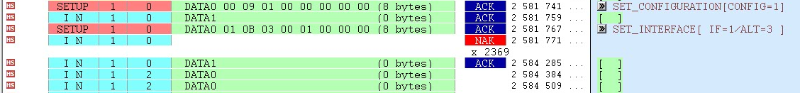
I think that enumeration is almost done, but I can't correctly receive the data packet with the isochronous IN token through EP2.
After issuing the IN token to EP2, a zero byte data is sent from the camera. A receive interrupt is generated and RXPKTRDY of HOST_RXCSR is set. At this time, FIFOFULL is also set for some reason. RXCOUNT is zero. When FLUSHFIFO of HOST_RXCSR is set, FIFOFULL is cleared. However, when issuing an IN token again, the zero data is received and FIFOFULL is also set.
As a test, when connecting the camera to the Laptop PC, the zero data is sent at the beginning and about 1000 bytes of data is gradually sent. The problem is not the recieving the zero data, but FIFOFULL is set despite the zero data. I attached a USB protocol analyzer log. In this log, two IN tokens are issued to EP2, but when it receives a zero data for the first IN token, FIFO becomes full.
EP2 and FIFO have the following settings.
- HOST_RXCSR (0x01E00526): 0000h
- INDEX (0x01E0040E): 02h (FIFO index for EP2)
- RXFIFOSZ (0x01E00463): 07h (FIFO size is 2048)
- RXFIFOADDR (0x01E00466): 0100h (Start Address is 800h)
- RXFUNCADDR (0x01E00494): 01h (The device address is 1)
Please give me some advice.
Regards,
Kzk
Part Number:TDA2PXEVM
Tool/software: TI C/C++ Compiler
Hi,
As discussed under "e2e.ti.com/.../2823318 creating the new thread related to compiler issues.
With the help of the patch we could compile the sources for A15 core both in module as well as in usecase.
The MAKEFILE.MK file what we have at our end doesn't contain anything related to "AUTOSAR_APP". So, I haven't included those changes.
ifeq ($(AUTOSAR_APP), yes)
-APP_LIBS_$(IPU_SECONDARY_CORE) += $(DEST_ROOT)/lib/$(PLATFORM)/$(IPU_SECONDARY_CORE)/$(PROFILE_$(IPU_SECONDARY_CORE))/app_libs.aem4
+APP_LIBS_$(IPU_SECONDARY_CORE) += $(DEST_ROOT)/lib/$(PLATFORM)/$(IPU_SECONDARY_CORE)/$(PROFILE_a15_0)/app_libs.aa15fg
endif
For your reference we are using below version of SDK "PROCESSOR_SDK_VISION_03_03_00_00"
You mentioned that you are running bios on A15 but your module uses linux calls......
Yeah, but can't we not overcome those compiler errors ?redefinition errors being
----------------------
/opt/V_SDK/FFC/FFC_WORKSPACE/scripts/..//sdk/ti/PROCESSOR_SDK_VISION_03_03_00_00/ti_components/os_tools/bios_6_46_04_53/packages/ti/sysbios/posix/mqueue.h:63:0: error: "O_CREAT" redefined [-Werror]
#define O_CREAT 0x200 /* TODO: sys/fcntl.h? */^
In file included from /opt/V_SDK/FFC/FFC_WORKSPACE/scripts/..//sdk/ti/PROCESSOR_SDK_VISION_03_03_00_00/ti_components/os_tools/bios_6_46_04_53/packages/gnu/targets/arm/libs/install-native/arm-none-eabi/include/sys/fcntl.h:4:0,
from /opt/V_SDK/FFC/FFC_WORKSPACE/scripts/..//sdk/ti/PROCESSOR_SDK_VISION_03_03_00_00/ti_components/os_tools/bios_6_46_04_53/packages/gnu/targets/arm/libs/install-native/arm-none-eabi/include/fcntl.h:1,
from /opt/V_SDK/FFC/FFC_WORKSPACE/source/vision/platform/ti/tda2/apps/src/rtos/modules/LibDLT/dlt_user.c:43:
/opt/V_SDK/FFC/FFC_WORKSPACE/scripts/..//sdk/ti/PROCESSOR_SDK_VISION_03_03_00_00/ti_components/os_tools/bios_6_46_04_53/packages/gnu/targets/arm/libs/install-native/arm-none-eabi/include/sys/_default_fcntl.h:37:0: note: this is the location of the previous definition
#define O_CREAT _FCREAT
^
-----------------------------
If you are running bios on A15 then all those answer does not hold true....
Yeah, I understand the answer doesn't hold true if either SYSBIOS runs of A15.
Having it in mind I would like re-iterate the set of queries to proceed further.
As Pthread support is available for A15, building pthread application for SYSBIOS would still be possible?
As mentioned our application had got sockets and FILESystem calls in place, Do we have support for FileSystem and sockets on SYSBIOS? If So, how could we make use of it or do we need to look for corresponding alternatives in it?
And having said Sample being the server component, there are the other applications which communicates to Sample via Sockets or through PIPES or any file based operations. Being Sample built for A15 core, does the other applications which has to communicate to Sample should also be built for A15?or IPC(shared memory) mechanism suggested still holds good for communication?
So you have to try with tda2px_evm_linux_all cfg....
Could please elaborate on it, what excatly should be considered from tda2px_evm_linux_all cfg.file reason being tda2px_evm_linux_all cfg.file had got A15_TARGET_OS to Linux.
Pradeep
Part Number:TDA2PXEVM
Tool/software: Linux
I have a TDA2PxEVM board mated to a custom board with cascaded AWR1243 radar chips. Currently we are streaming all the raw data from the EVM to a laptop via Gigabit Ethernet, but the data rate of the cascaded chips exceeds what Gigabit Ethernet can handle, so I want to use USB 3.0. Eventually we will do processing in the TDA2px, but for now we want to log and process the data on the laptop.
I was told previously that the best way to use USB is to run Linux on the A15 core. I have a Ubuntu 18.04LTS development system. I am new to USB development and would like more specific advice about the best (and easiest) way to stream data over USB 3.0 and achieve as close to the 5 Gbps theoretical limit as possible.
Questions:
Thanks!
Part Number:ADC128S102
Hello,
Here i am facing problem of signal cross talk between ADC128 consecutive channels,
so when i apply some high Voltage say 5 V on 1st channel of ADC and 0 V on 2nd channel of ADC and rest of the ADC Channels are also on 0 V , and i send instruction to read all 8 channel of ADC so i get result as,
1st channel = 4095
2nd channel = 18 #problem is here i should get 0 digital reading here because i applied 0 V on this channel
3rd channel = 0
4th channel = 0 and so on all 0 digital reading till 8 channel,
and this problem is constantly repeating and also when i apply high voltage on other channel say 3rd channel and all other channels are grounded so i see the high voltage effect of 3rd channel on 4th channel,
So basically when i apply high voltage on a channel of ADC it is effecting the Next channel so i need a solution on how to avoid or rectify this problem ?
Part Number:TLC5958
Dear TI Experts,
From the datasheet, TLC5958 can support 20ma per channel @3.3V VCC.
Is there another device which can provide 35~40mA per channel and at least 48 channels? I find LP5036 can provide 35mA per channel, yet there are only 36 channels.
Could you kindly give some advices for this requirement? Thanks a lot.
Part Number:TMS320F28234
Tool/software: Code Composer Studio
I am using XDS100V2 emulator to load the program to RAM using code composer stuido. But when working with high voltage , the connection between the emulator and the Code composer gets terminated abruptly.
When i checked the XDS100V2 emulator schematic , i came to know that it does not have any isolation.But all the evaluation boards from TI, is supported with On board emulation with isolation.
I need to add isolation to XDS100V2 signals. Can anyone suggest a cheaper option ?
Part Number:DRA72XEVM
Tool/software: Linux
Hi TI,
I am using PROCESSOR_SDK_VISION_03_04_00_00.
Having new usecase :-
NullSource (A15) -> Decode -> VPE -> Dup -> Merge -> Sync -> Alg_DmaSwMs -> Merge_1
DispDistSrc_weston -> Merge_1
Merge_1 -> Display
Links are created and video is playing in video layer.
Grapahic layer is also running.., but is not visible to display ?
Is it necessary to modify display controller tree to support graphic layer ?
I have validated separate usecase (video as well as graphic layer) without any issue !!!
Merged this usecase into one, I did'nt get any error, video is playing, graphic layer is not visible, by seeing the logs is running in the background ?
Kindly suggest me to solve this issue !!!
Regards,
Rajesh Kannan S