Quantcast
Channel: Forums - Recent Threads
Viewing all 262198 articles
Browse latest View live

TSW1400EVM: TSW1400EVM: HSDC Pro v5 shows "No firmware. Please select a device to load firmware into the board." With AFE5808EVM board.

$
0
0

Part Number:TSW1400EVM

Problem:

HSDC shows "No firmware. Please select a device to load firmware into the board."  on startup and use of the board.

Pertinent information:

-The board turned on and loaded the firmware 3 times correctly before this occurred. No significant experiments were completed beyond configuration test. The Problem, First experienced late november 2018.

-The SOP outlined in TSW1400 and AFE5808EVM was always observed when using the board for experiments. When not in use boards were stored in ES Shielded packaging in a dry clean place.

-The  AFE5808EVM can communicate and function correctly with the AFE5808EVM GUI independently and can be ruled out as the problem.

-The TSW1400 was purchased around March of 2018, however was not opened until September 2018

-HSDC can identify the TSW1400's serial number and presence

-The PSU in use is a laboratory benchtop module operate at 5V with an Amp cap at 5A, It never would draws more than 3 Amps at any time.

-Host computer Windows 10 64x Surface Book 3

Solutions Tried:

As outlined in the similar problem found in https://e2e.ti.com/support/sensors/f/1023/t/699148#pi320995=2

- Ensured that the voltage received is exactly 5V and tested up to 5.4V from across  TP22 GND testpoint for the negative, and the metal tab at the back of the J12 +5V_IN connector as the positive measurement point.

-No firmware loads to the board/ gives same error, tested were the "ADS5294_1W_12b", "ADC_FIRMWARE", and "AFE5805_x12" which originally worked

There is very little information to go off with this error message, If any of the TI employees could give recommendation we can test them as soon as possible. If you feel that this is in a condition that requires to be replaced what options do we have available to do this considering it is a very expensive board that never was really used.


LM96163: how to disable D+/D- ?

$
0
0

Part Number:LM96163

Hi Team,

If customer only wants to use this device to generate a fixed frequency and duty cycle and not going to use temperature sensing feature, what should we do to disable sensor side (like D+ and D-)?

My little idea is to fill up 12 LUT index same PWM frequency and PWM duty cycle if we cannot disable the sensor.

Please give me suggestion, thanks!

Andrew

TI Precision Lab_SAR

$
0
0

Dear TI Precision lab, 

While I was studying the material regarding Introduction to SAR ADC of TI precision lab SAR, I got a question about the bucket capacitor and Resistor as shown in the attachment. 

I believe this signal chain is after the anti-aliasing filter and the purpose of Cfilt and Rfilt is to overcome the spiky response from the sampling capacitor and better for the settling. But if the calculated RCfilt corner frequency is not the same as the anti-aliasing filter, for example, smaller or larger than that. Whether it will truncate the signal bandwidth or introduce aliasing? 

Thank you very much, 

B.Fan

LAUNCHXL-CC2650: Hoe Notification is received in a Central Profile

$
0
0

Part Number:LAUNCHXL-CC2650

Where exactly will the notification be received in the central profile and how to get the notification value? 

LMK04826: duty cycle of its clock input??

$
0
0

Part Number:LMK04826

hello

in a previous post, I had asked if the LMK04826 can be used in a system with a varying duty cycle signal at its CLKIN inputs.  Anyhow the response was that the LMK looks at the rising edges so it should work with our CLK input.

Anyhow I would like to attach a pdf that shows the clock signal that we are using but your forum doesnt permit it.  Is there a way for me to provide you a waveform?  For now you can think of a waveform where its HIGH for 3 system clock cycles, then OFF for 1 system clock cycle and then ON for one system clock and then OFF for one system clock cycle and then it finally repeats itself.  its 1 WIDE PULSE followed by 1 narrow pulse before repeating itself.

Right now the LMK indicates that PLL1 is NOT LOCKED.  However after using the status pins to output the INTERNAL DIVIDERS, we can clearly see that the dividers are working correctly and furthermore, the divided frequency into the PLL1 IS CORRECT. 

Can anyone explain to us why the LMK reports that PLL1 is not locked but internal circuitry seems to be OK?  We even increased the LOCK window size and still NO LOCK.  We can only guess that this part does not like clk inputs that do not have 50 % duty cycle which is different from what we were initally told.

Is this the problem or should we be looking elsewhere??  

Please assist.  

Thanks

LM5066I: LM5066IEVM-626 Evaluation Modules dead on arrival?

$
0
0

Part Number:LM5066I

I have ordered 3 LM5066IEVM-626 Evaluation Modules directly from TI and none of them will communicate with my computer. Here are the issues that I have with this development platform;

  1. The documentation is out of date; it references a program that is obsolete and no longer supported as mentioned by a member here. The software provided with the board is PI-Commander but the entire manual references "PMBUSMGR GUI" so I'm not really sure why I am so surprise that I can't communicate with the board.
  2. The boards that I have ordered will not communicate with the provided drivers. I have been able to establish no communication whatsoever after trying on several different Windows operating systems (windows 7, windows 2010 twice). I was recommended to re-install the drivers several times and that simply does not work. As far as I can tell the boards are dead on arrival. If there is a quality sticker on the board that verifies that it was working at some point I would like to know so I can check that this board was ever verified to have been working. In total I have spent ~12 hours troubleshooting brand new boards for basic communication. The idea of an evaluation board is supposed to get you up and running as quick as possible, this has been anything but that. 

I have tried to escalate numerous times, sent several emails to the support member assisting me and I still haven't heard from anyone.

Please help escalate so I can get a working board in my hands asap.

Ray

Reading Manufacturing Status via SMBus from a BQ40Z50

$
0
0

Hello,

I am using an STM32L476G Discovery board to communicate with a BQ40Z50EVM-561 via SMBus. I’m having trouble understanding how to handle reading and writing from the Manufacturing Access System (MAC) as described in the technical reference manual for the BQ40Z50EVM. My specific goal is to be able to read the status of CHG/DSG FETs and then change their state. I can successfully read several parameters already, (Voltage, Current, SoC) etc. but it is unclear how I should change my existing functions to implement the SMBus block read/write protocol as described in section 13.1 of the gauge TRM.

Some of the code I am using to read voltage from the gauge is as follows:

// Address for voltage given in gauge TRM

writeData = 0x09;

// Voltage word size

size = 2;

HAL_SMBUS_Master_Transmit_IT(&hsmbus1, 0x0B << 1, writeData, size, SMBUS_AUTOEND_MODE);

Should I just be able to change “writeData” to 0x0057 (the Manufacturing Status address, which contains FET states) and “size” to 4?

Any suggestions of resources or example code you could point me to would be greatly appreciated.

Thank you.

Linux/MMWAVE-SDK: Cannot install mmWave in at least 4 Linux-distros

$
0
0

Part Number:MMWAVE-SDK

Tool/software: Linux

Dear all,

I apologize for duplicating the thread, but my former question was closed before I get this new information 

My steps are:

1) download the file mmwave_sdk_03_01_00_02-Linux-x86-Install.bin

2) chmod +x mmwave_sdk_03_01_00_02-Linux-x86-Install.bin

3) ./mmwave_sdk_03_01_00_02-Linux-x86-Install.bin

after the <ENTER>, waited half a second and the cursor came back, ready for the next command.

4) sudo ./mmwave_sdk_03_01_00_02-Linux-x86-Install.bin

same result.

5) ./mmwave_sdk_03_01_00_02-Linux-x86-Install.bin -h/--help/--version.....

no output, no complaint, nothing missing, etc... SILENCE!

The news is that I tried this installation in several distros:

1) Mint 19

2) Debian 9

3) Ubuntu 18.10

4) Ubuntu 16.04 (referred in the Release Notes)

Does anyone can share what the dependencies of this tools are? What are the possible reasons to fail without a reason?

Thanks in advance,

Luciano


TI Cross for Audio Codec

$
0
0

Hello, 

This is a bit of a long shot, but I'm looking for a TI cross for an audio codec part, the Realtek ALC3264. I wasn't able to find a datasheet or any solid specs online, but I was hoping maybe someone in the forum knows anything about it. 

Thanks in advance!

-Olivia Morell 

DP83630: About thermal resistance (Tja)

$
0
0

Part Number:DP83630

Hello,

Regarding to thermal resistance (Tja) on DP83630, my customer is asking some question.

(Question)

(1) Could you please tell us about this data? (It is not described on datasheet.)

(2) Also can we estimate it same as Tja of other WQFN(48) device?

(It is about 24-30° C/W.)

(3) The Tja is only in condition of Junction-to-ambient and It doesn't consider the thermal pad.

My understanding is correct?


Regards,

Tao 2199

TPS706: Tying two LDO outputs together to get different voltages

$
0
0

Part Number:TPS706

I have a case where Vin is pulled from a 3.6V LiPo. To extend unit lifetime, we really want to run it right down to 3.0V. Iq is important.

Sometimes, the load needs to be driven with 3.3V. That will only happen when the charger is connected, so Vin will be >= 3.6V.

Most of the time, the load only needs 2.7V. That's the period where we need to be able to discharge the cell down to 3.0V.

It seems like we could use two TPS706s, one set for 3.3V and one set for 2.7V, with their outputs tied together. We'd use the enables to enable the correct one at the correct time.

In that application, am I correct in thinking that with the 3.3V regulator disabled (EN pulled low), the reverse current protection will keep Iq for both regulators low (<1uA) and allow the active regulator to operate correctly?

A different way to do this might be with a conventional adjustable LDO, with an extra leg on the FB controlled by a FET, so that one of the voltage-setting resistors effectively has two values.

UCC21540: for 600V GaN drive

$
0
0

Part Number:UCC21540

Hi all,

In the data sheet of UCC21540 GaN characters are on it.

Which manufacturers 600V GaN match for?

Or someone tried any 600V GaN?

TINA/Spice/LM34936: PSpice model for simulating the input line regulation

$
0
0

Part Number:LM34936

Tool/software:TINA-TI or Spice Models

HI, LM34936 support team

I would like to simulate the input line regulation of LM34936 when LM34936 was used at the back of PD controller because it must support the input voltage range of 5V-20V. There is a "LM34936 PSipce Transient Model" as simulation file in product folder. There are 2 kinds of schematics for simulation as follows. But PSpice library is only one.   


1. Is the same PSipce libray file used to simulate for Start-up and Steady_State?

2-a. If YES, is the difference between Start-up and Steady_State only the input power supply model?

2-b. If NO, which schematic of Start-up and Steady_State should I use to simulate the input line regulation?

Regards,

Tamio

TMDSEVM572X: ESD Protection for HDMI on TMDSEVM572X

LM46002: RoHS2

$
0
0

Part Number:LM46002

Hi, team.

Does LM46002PWP conform to RoHS status (10 substances) 2011/65/EU(RoHS2) ?

Best Regards,


TPS7A87: RoHS2

$
0
0

Part Number:TPS7A87

Hi, team.

Does TPS7A8701RTJ conform to RoHS status (10 substances) 2011/65/EU(RoHS2) ?

Best Regards,

TPS65987D: USB Type-C port protector with TPS65987D

$
0
0

Part Number:TPS65987D

Hi Team,

My customer considers to use TPS65987D for PD controller.
Regarding USB Type-C port protector, there is TPD8S300A (4ch D+/D- IEC ESD) and TPD6S300A (2ch D+/D- IEC ESD) .
Which device should be used with TPS65987D?
I believe TPD6S300A is sufficient however would like to confirm just in case. 

Best Regards,
Yaita

66AK2G12: Sticky error in EDMATC_ERRSTAT Register

$
0
0

Part Number:66AK2G12

Hi,

My customer noticed that MMRAERR on EDMATC_ERRSTAT register was sticky even if they clear the bit via EDMATC_ERRCLR register.
I recreated the same problem on my EVM, see below:

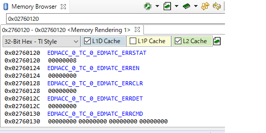
1. launch CCS and connect to C66 core with default gel file and then open memory browser. If you navigate EDMATC_ERRSTAT register, MMRAERR has been set by default. Not that EVM has been powered with No Boot configuration.

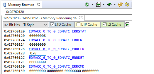
2. Try to clear the bit via EDMATC_ERRCLR register

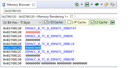
3. The bit looks cleared ...

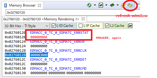
4. But if you update the window, the error raised again.

For now, they has been able to use EDMA normally on their board, but how should we handle this error ?

Best Regards,
NK

Linux/AM3505: Forking on 2.6.37 kernel fails randomly

$
0
0

Part Number:AM3505

Tool/software: Linux

Q1: We have been experiencing a random kernel crash on our radio with AM3505 and Kernel 2.6.37 and wondering if any patches from TI could be involved?

Even if this isn't relevant to Texas Instruments would appreciate you know of someone else in the forum have reported something along these lines,

[115471.753753] kernel BUG at mm/prio_tree.c:79!

[115471.753784] Unable to handle kernel NULL pointer dereference at virtual address 00000000

[115471.753814] pgd = c60f8000

[115471.753814] [00000000] *pgd=86062031, *pte=00000000, *ppte=00000000

[115471.753845] Internal error: Oops: 817 [#1]

[115471.758239] last sysfs file: /sys/devices/virtual/fpga_ctrl/fpga_ctrl/energy_save

[115471.766174] Modules linked in: heartbeat mdl_driver omap3_crypto rohc gpio_driver fpga_driver spi_fpga

[115471.776031] CPU: 0    Not tainted  (2.6.37 #2)

[115471.780822] PC is at __bug+0x1c/0x28

[115471.784667] LR is at __bug+0x18/0x28

[115471.788482] pc : [<c004139c>]    lr : [<c0041398>]    psr: 20000093

[115471.788513] sp : c6093ec8  ip : 00006528  fp : c61dc498

[115471.800720] r10: 0000000b  r9 : c61dc4b4  r8 : c61dc4b8

[115471.806274] r7 : c607a500  r6 : c67dbac8  r5 : c60d3ac8  r4 : 401a5000

[115471.813201] r3 : 00000000  r2 : c6093ebc  r1 : c041a567  r0 : 00000037

[115471.820159] Flags: nzCv  IRQs off  FIQs on  Mode SVC_32  ISA ARM  Segment user

[115471.827819] Control: 10c5387d  Table: 860f8019  DAC: 00000015

[115471.833923] Process stat_manager (pid: 4542, stack limit = 0xc60922f0)

[115471.840881] Stack: (0xc6093ec8 to 0xc6094000)

[115471.845550] 3ec0:                   00000044 c00ab73c c612ecc0 c0060d48 c61f1ec0 c607a534

[115471.854217] 3ee0: c612ecf4 c61dc4a4 c04dacd4 c615a800 01200011 00000000 c615a8f0 00000000

[115471.862884] 3f00: 40358068 c60b9dc0 c04dacb0 c0061508 000030b0 c04bf1e8 00000001 beeeaa58

[115471.871551] 3f20: c6093fb0 00000000 00000000 00000000 00000001 01200011 00000000 c6093fb0

[115471.880249] 3f40: 00000000 00000000 beeeaa58 00000000 beeeaa9c c0061c80 40358068 00000000

[115471.888916] 3f60: 00000000 00000000 00000000 beeeaab8 00026008 00000167 c003dc08 beeeaab8

[115471.897583] 3f80: 00000008 00000000 40358068 beeeaa58 000011be 00000078 c003dc08 c6092000


[115471.906250] 3fa0: 00000000 c003da60 00000000 40358068 01200011 00000000 00000000 00000000

[115471.914947] 3fc0: 40358068 beeeaa58 000011be 00000078 40349000 40358000 4034c2b8 beeeaa9c

[115471.923614] 3fe0: 403584c0 beeeaa58 000011be 402b4ff8 60000010 01200011 87ffe021 87ffe421

[115471.932312] [<c004139c>] (__bug+0x1c/0x28) from [<c00ab73c>] (vma_prio_tree_add+0x4c/0xbc)

[115471.941101] [<c00ab73c>] (vma_prio_tree_add+0x4c/0xbc) from [<c0060d48>] (dup_mm+0x22c/0x3a0)

[115471.950134] [<c0060d48>] (dup_mm+0x22c/0x3a0) from [<c0061508>] (copy_process+0x61c/0xc28)

[115471.958923] [<c0061508>] (copy_process+0x61c/0xc28) from [<c0061c80>] (do_fork+0x148/0x304)

[115471.967773] [<c0061c80>] (do_fork+0x148/0x304) from [<c003da60>] (ret_fast_syscall+0x0/0x30)

[115471.976715] Code: e59f0010 e1a01003 eb0cb1b3 e3a03000 (e5833000)

[115471.983398] ---[ end trace be115207729a3577 ]---

Q2: The side effects of this problem is a device reboot, hence a general question to the CPU reset source. Is there any way to know from the CPU how it was reset (after it has been reset), i.e. which type of reset triggered the reboot?

Appreciate your attention.

Regards,

Yakir M.

MiMOMax Wireless Ltd.

DP83822I: Line driver for FLP

$
0
0

Part Number:DP83822I

Hi Team,

Could you give me comments on following customer question?

<Customer question>

Is the same or different line driver used for 100BASE-T and 10BASE-Te? If different line driver is used, is FLP burst generated from the line driver for 100BASE-T?

Thank you for your support. 

Best regards,

Takeshi Sasaki

Viewing all 262198 articles
Browse latest View live


<script src="https://jsc.adskeeper.com/r/s/rssing.com.1596347.js" async> </script>