Quantcast
Channel: Forums - Recent Threads
Viewing all 262198 articles
Browse latest View live

ADS1292R: Plz, help me.

$
0
0

art Number:ADS1292R

I'm not used to Eng.

I can read test signal well. 

*Sampling rate 250Hz

y-axis is mV, x-axis is sample number.

But I can't read correct signal from electrodes that were connected with CH1. and the signal was 3Hz-50mVpp-Sine wave from function generator.

*Sampling rate 500Hz.

y-axis is mV, x-axis is sample number.

It is similar 3Hz(three periodic wave in 500 samples, 1 sec) but with only positive polarity. and also the amplitude is not correct.

So I changed polarity of input cable. then,

 ...

I want to read whole sine wave. why these error occurs? my schematic is

VREF was well measured at 2.42V

and register set 

write_reg(0x01, 0b10000010);
write_reg(0x02, 0b10100000);
write_reg(0x03, 0b00010000);
write_reg(0x04, 0b00000000);
write_reg(0x05, 0b10000000);
write_reg(0x06, 0b00000000);
write_reg(0x07, 0b00000000);
write_reg(0x08, 0b00000000);
write_reg(0x09, 0b00000000);
write_reg(0x0A, 0b00000011);
write_reg(0x0B, 0b00000000);

plz, help me.


LM2902KAV: Variation of voltage in Opamp

$
0
0

Part Number:LM2902KAV

I am using LM2902KAVQDRQ1 for analog voltage amplification as shown in the circuit. The full circuit has a gain of 1.62 and the input range is from 0 - 1.88 V. The problem is that there is a variation of 5-20 mV at the output side(PIN NO 14). The resistor tolerance is 1% and capacitor tolerance is 5% in the circuit.  Can you please suggest any improvements ?  

Regards

Daivik

CCS/TMS320F28335: Error while conncecting to the target

$
0
0

Part Number:TMS320F28335

Tool/software: Code Composer Studio

Hi ,

I am facing while connecting to the target , previously it was working fine , suddenly am facing the below problem ,

Error connecting to the target:
(Error -151 @ 0x0)
One of the FTDI driver functions used during the connect
returned bad status or an error. The cause may be one or
more of: no XDS100 is plugged in, invalid XDS100 serial number,
blank XDS100 EEPROM, missing FTDI drivers, faulty USB cable.
Use the xds100serial command-line utility in the 'common/uscif'
folder to verify the XDS100 can be located.
(Emulation package 6.0.407.3)

Please help me in clearing this error .

Thank you

Regards ,

Hanitha

CC1352R: CC1352 Internal DAC driving external load

$
0
0

Part Number:CC1352R

HI, 

trying to understand from the TRM whether the Internal reference DAC can be used to drive an external pin and what the limitations are. The text in sections 19.5.5.2.4 Output Selection, and 19.5.5.2.4.2 seem to indicate that this is possible as long as DAC buffer is also used. It also references a special API that should be used with no reference to the API documentation - can you pls detail what this is ? thanks.

BQ4050: Bq4050EVM-561

$
0
0

Part Number:BQ4050

We are drop this project just because of Data flash read and write problem and going in loss too.

Thanks for the support.

Regards

Rahul Kumar (VNL)

BQ4050EVM-561: bq4050

$
0
0

Part Number:BQ4050EVM-561

We are drop this project just because of Data flash read and write problem and going in loss too.

Thanks for the support.

Regards

Rahul Kumar (VNL)

TMS320F28377S: Can we ignore F2837xS Silicon Errata "Low-Power Modes: Power Down Flash or Maintain Minimum Device Activity" ?

$
0
0

Part Number:TMS320F28377S

Hello,
we have no plan to use HALT, STANDBY, IDLE and other low-activity conditions on our F2837x board.
In our case, can we ignore the following F2837x errata ?

TMS320F2837xS Silicon Errata www.ti.com/.../sprz422g.pdf
On page 24, Advisory: Low-Power Modes: Power Down Flash or Maintain Minimum Device Activity

It mentions that H/W modification to add 82 Ohm resistor as workaround 3.

Best regards,

ay0689

LM3414: lm3414 LED driver initial rush current when load conected

$
0
0

Part Number:LM3414

Hello , 

i am using LM3414 for LED string (4 LED in series ) driver . Power supply 18~ 24V . LED VF = 2.82 V/ LED 

please see attached schematics  . when switch B closed (2LED in CIRCUIT  ) , When Switch A is close from open condition , rush ciurrent peak occur which is more than 1.5A .

but when switch B open (4 LED in circuit ) and switch A open to close no much inrush peak occure ( less than 1.5A )

Please help how to reduce that peak above 1.5A ???


LM5145: Could you please tell me any countermeasure to reduse high side gate ringing on EVM board?

$
0
0

Part Number:LM5145

 Hello guys,

 One of my customers is evaluating LM5145 using  LM5145EVM-HD-20A (http://www.tij.co.jp/jp/lit/ug/snvu545a/snvu545a.pdf) for their new products.

 But they can't buy Infineon device dut to their distribution channel. So they replace BSC117N08NS5 for Q1 and BSC037N08NS5 for Q2 on EVM

with TI, CSD19531Q5A for Q1 and CSD19533Q5A for Q2. Also they change the following spec of EVM too.

1. EVM output voltage: 5V -> 12.5V.

2. Output capacitor: 47uF*7 -> 47uF*1.

3. Inductance, L2 , 3.3uF -> 15uF.

4. Switching frequency: 220kHz -> 370kHz

5. Input voltage: 24V

 When they measured effeciency of the EVM, the effeciency is about 90%. They thought it is low effeciency. So they cheched the gate voltage of Q1 and Q2.

As the result, they found Q1, the gate voltage of CSD19531Q5A(High side FET) was ringing dutring about 100ns with 5V swing  .

They think the high side NMOSFET, CSD19531Q5A could not be used with LM5145 because of high speed turn on/off characterstics.

 They wants know whether it is not good to use CSD19531Q5A for high side NMOSFET with LM5145 or not.

 Could you please give us any comment? And if you have any idea, could you please tell us any TI NMOSFET part number for the high side NMOSFET?

 Your reply would be appreciated.

 Best regards,

 Kazuya Nakai.


DRV595: Power supply of Mode select pin

$
0
0

Part Number:DRV595

Hi shawn,

For the SDZ and MOSEL pin, must this pin use the AVCC or PVCC?

I find the VIH of this pin is 2V, so can we use resister to pull up this pin to 3.3V and make sure the high level voltage is larger than 2V?

Another question is about the AVCC and PVCC, can I use the same DCDC or LDO to supply the AVCC and PVCC?

Lacey

Thanks a lot!

TM4C123GH6PM: Firmware upgradation of TM4C123GH6PM through CAN

$
0
0

Part Number:TM4C123GH6PM

Hi,

I am using boot_serial example provided by TI to upgrade the firmware using CAN. Can you please answer the following queries

1. What changes i have to make in the boot_serial example code for using it with CAN communication

2. How to test if the bootloader is working with CAN communication (How to send application binary file using CAN bootloader)

3. What is the use of CAN_UART_BRIDGE. Do we need to use this for CAN bootloader code?

4. How to jump from application to bootloader for application directed firmware upgrade.

Thank you

Best Regards

DS90UB953-Q1: how to get S11 and S12 parameter of DS90UB953 to DS90UB954 for simulation

$
0
0

Part Number:DS90UB953-Q1

Dears,

   I use DS90UB953 and DS90UB954 in my ADAS product. I want to simulate the transmit-ion  of DS90UB953 to DS90UB954 .

So I want to know the minimum requirements for the s11 and s12 parameter  that enable the DS90UB953 and DS90UB954 to communicate smoothly.

CC2564: How to set L2CA_Queueing_Parameters

$
0
0

Part Number:CC2564

Hi,

May I know how to set the parameters in L2CA_Queueing_Parameters_t so that it will behave like streaming device with lowest latency?

I am using HIDDemo sample code.  May I know the appropriate value for each parameter?

typedef struct _tagL2CA_Queueing_Parameters_t
{
DWord_t Flags;
DWord_t QueueLimit;
DWord_t LowThreshold;
} L2CA_Queueing_Parameters_t;

ret_val = HID_Set_Data_Queueing_Parameters(BluetoothStackID, &Queue_Para);

thanks.

skv 

66AK2G12: DDR_PHY_PGCR1 register in calc tool

$
0
0

Part Number:66AK2G12

Hello,

WLMODE and PHYHRST bit-fields indicate 1 and 0 respectively in the register calc tool (K2 DDR3 Register Calc v1p60.xlsx), and it looks these has been changed from its default value (WLMODE=0, PHYHRST=1). In the cal tool, those bit-fields are grayed out and the "instruction sheet" suggests it should the default value.

So my question here is, which values should we use for these bit-fields in DDR3L initialization, the value from the calc tool, or the default value ?

Best Regards,
NK

Compiler/TMS320F28377D: Section allocation problem

$
0
0

Part Number:TMS320F28377D

Tool/software: TI C/C++ Compiler

Question 1:

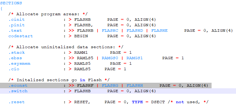
The compiler creates many sections such as .econst, .ebss as shown below

.econst section is restricted to anywhere in data. However, the sample cmd file(2837xD_FLASH_lnk_cpu1.cmd) provided by TI allocates .econst  section to program memory (PAGE 0).

I think it should be allocated to PAGE 1. Is that right?

Question 2:

After DSP is secured, DATA reads to a secure memory are always blocked unless the program is executing from the secure memory. I want to know what the exactly definition for "DATA Read".

In other words, which sections does the DATA include? .binit, .cinit, .econst, .ebss, .stack, .esysmem, .switch?


IWR6843: TX beam forming

$
0
0

Part Number:IWR6843

Hello,

Does IWR6843 support Tx beam forming?

Section 6.3.1.2 Transmit Subsystem in the datasheet describes that "The device supports 6-bit linear phase modulation for MIMO radar and interference
mitigation."
Does the phase shifter support 5.625 degree/bit for each TX channel?
Is simultaneous 3ch TX supported for TX bean forming?

Best Regards,
Katsuhiro

TPS23521: TPS23521 power capability

LMK04906: About DC coupling and AC coupling of CLKin, OSCin

$
0
0

Part Number:LMK04906

Hi all.

I would like to the different between "Single-Ended Termination"(Figure 24) and "DC Coupled LVCMOS/LVTTL Reference Clock" (Figure 25).
What is definition of single-end?
I think LMK04906's recommended termination is AC coupling when clock source is single-end, If we refer to Figure 25 with using single-end. In this case, is it any issue?

Sorry, I would like to get your comment as soon as possible.

Best regards,
Sho 

CC2541: CC2541 (CC2543)

TDC1000: Ultrasonic Analog Front End TDC1000 for measuring Metal Thickness

$
0
0

Part Number:TDC1000

I am researching for a new project in which objective is to measure Metal Plate thickness which is in the range of 2 mm to 50 mm. Technology would be Ultrasonic Echo reading. 

Application - Many applications are listed like Flow, Concentration, Distance and Fluid ID in TDC1000 Datasheet. But no where mentions Thickness Measurement, specially Metals.

Methodology - Trigger a pulse on plate surface and record TOF for first few responses by TDC7200. Then Application specific logic with the help user set other physical parameters like sound speed in material, controller will determine thickness mathematically.

Question is, weather TDC1000 along with TDC7200 will be capable of doing so? I wish to capture echos from metal medium. 

I have not selected any parts for this. Please suggest any other parts that suits better. 

If above parts are capable of doing so then I should proceed for EVM and testing. Please so ask for any query.

Thank You.

Viewing all 262198 articles
Browse latest View live


<script src="https://jsc.adskeeper.com/r/s/rssing.com.1596347.js" async> </script>