↧
TPS549D22: VBP voltage when VDD is lower than 5.07V
↧
TPS54317: I want to know the date code of TPS54317
↧
↧
CC2530 HEX printout
Hi Guys,
I working to integrate my core dimmer to an exchange, device that working well with zero crossing detector, via Uart using an existent protocol.
My device running over Zstack Z-Stack Home 1.2.2a.44539 referenced to CC2530 HA Sample light switch project.
I have started my dimmer with this configuration:
Hal_board_cfg: CC2530EB
Compiler options for Uart settings: ISR_KEYINTERRUPT, HAL_UART=TRUE, HAL_UART_ISR=1 and HAL_UART_DMA=FALSE
Settings in my C file:
UART Start
// This app is part of the UART Init - Port 0 P0_2/P0_3 RX/TX
void initUart0(halUARTCBack_t pf)
{
HalUARTInit();
halUARTCfg_t uartConfig;
uartConfig.configured = TRUE;
uartConfig.baudRate = HAL_UART_BR_115200;
uartConfig.flowControl = FALSE; // need to configure it as No flow control in Remote Terminal.
uartConfig.flowControlThreshold = 48;
uartConfig.rx.maxBufSize = 128;
uartConfig.tx.maxBufSize = 128;
uartConfig.idleTimeout = 6;
uartConfig.intEnable = TRUE;
uartConfig.callBackFunc =pf;
//start UART
//assumes no issues with starting UART
(void)HalUARTOpen(HAL_UART_PORT_0,&uartConfig);
}
void uart0RxCb( uint8 port, uint8 event )
{
uint8 ch;
while (Hal_UART_RxBufLen(port))
{
// Read one byte from UART to ch
HalUARTRead (port, &ch, 1);
}
}
My device init:
initUart0(uart0RxCb);
My new function that is not working well:
/*********************************************************************
* @fn zclTTa0003_UartSEND
*
*/
void uart0Send(uint8* uartTxBuffer, uint16 uartTxBufLength)
{
// Clear any pending TX interrupt request (set U0CSR.TX_BYTE = 0).
U0CSR |= 0x80;
// Loop: send each UART0 sample on the UART0 TX line.
for (uartTxIndex = 0; uartTxIndex < uartTxBufLength; uartTxIndex++)
{
U0DBUF = uartTxBuffer[uartTxIndex];
while(! (U0CSR & 0x80) );
U0CSR &= ~0x80;
}
}
My new function called in on/off CMD:
if ( cmd == COMMAND_ON )
{
zclTTa0003_OnOff = LIGHT_ON;
#ifdef ZCL_MONITOR
//Output "UART debug output" to UART Port0
HalUARTWrite( HAL_UART_PORT_0, "Light is ON", (byte)osal_strlen("Light is ON"));
#endif
}
// Turn off the light Written ASA
else if ( cmd == COMMAND_OFF )
{
zclTTa0003_OnOff = LIGHT_OFF;
#ifdef ZCL_MONITOR
//Output "UART debug output" to UART Port0
uart0Send(uartTxBuffer, SIZE_OF_UART_TX_BUFFER);
#endif
The existent protocol have follow structure:
My dimmer (Master):
Exchange device (Slave):
Frame Format Structure:

The word sent by Master (my dimmer device):

When: AABB is a Duty Cycle value to setup the PWM Level in a exchange board.
I have in my mind to cut the word in 2 parts, 1st 055C010000000000000000, 2st AABB0000000000000000000000000000 and handling duty cycle in the 2st part. After it to merge in a function to send a complete word.
I need to build a SEND UART function, to send the word. I study UART Hal API and Didn´t find anything command to do that.
Before to send a HEX values in a new function I starting to test with string text, but i is not working, when my device call this new function stop to work.
Anybody have an idea how to build a function to send the word above?
↧
CCS: New workspace CCSv8 Getting Started error
Tool/software: Code Composer Studio
After creating a new "workspace_v8" on first launch "Getting Started" and launching "Resource Explorer" works OK. On the second launch I get a blank screen for "Getting Started". On the third launch of ccsv8 and "Getting Started" I get the following dialog box.
Problem Occurred - 'Getting Started Initializer' has encountered a problem. An Internal error has occurred.
Details - An internal error has occurred. The Chromium profile directory is already used/locked by another BrowserContext instance or process.
All other ccsv8 operations appear to be OK.
↧
TM4C1294NCPDT: basic ethernet controller samples for lounchpad 1294xl
Part Number:TM4C1294NCPDT
Hi, I'm trying to use the tiva 1294 lounchpad to test Internet connection, but I can't find samples program not related to rtos, nor complex stuff.. just send a Ethernet packet through the emac controller and receive something, I'm trying to use the driver library that has the emac interface, but it would be nice to have a working program to use as an example of how to use the driver. Of course that a tcp/ip sample program could help too. I'm compiling with gcc a blinky / uart and it works fine. I've no experience with lwip, so I'd prefer to begin with a bare code to understand the basics and maybe then I'll try lwIp or something like that. Any help would be apreciated. By the way I'm over linux. Thanks!
↧
↧
CCS/MSP430FR6989: Variable doesn't act the way it should in the debugger (CCS 6.1.0)
Part Number:MSP430FR6989
Tool/software: Code Composer Studio
Hi TI community,
I have an MSP430FR6989 uc, programming it using MSP-EXP430FR6989 launch pad, and I am using CCS 6.1.0
am doing a simple code, where I create an odometer that counts from 0 to 99,999, and then resets again.
This is my code.
#include <msp430.h>

#define DEVELOPMENT 0x5A80
#define ENABLE_PINS 0xFFFE

int main(void)
{
    WDTCTL = DEVELOPMENT;
    PM5CTL0 = ENABLE_PINS;//this is needed in order to enable pins

    P1DIR = 0x01;
    P1OUT = 0x00;

    unsigned int ones, tens, hund, thou, tnth;

    unsigned long km = 0;

    while(1)
    {
        for(tnth = 0;tnth<10;tnth++)
        {
            for(thou = 0;thou<10;thou++)
            {
                for(hund = 0;hund<10;hund++)
                {
                    for(tens = 0;tens<10;tens++)
                    {
                        for(ones = 0; ones<10;ones++)
                        {
                            km = 10000*tnth+1000*thou+100*hund+10*tens+ones;
                        }
                    }
                }
            }
        }

        P1OUT = ~P1OUT;
        km = 0;
    }

return 0;
}
I added a breakpoint at P1OUT = ~P1OUT , and pressed the Resume button. (Line 41)

At that line, I see the values of tnth , thou , hund , tens , and ones are equal to 10 , which is as expected.
But I also expected km = 99999 , but instead I got km = 34463 . Shouldn't km = 99999.
Also
I modified my code, and changed thnth , thou , hund , tens , and ones to signed int instead of unsigned int
when I Run my program, and it reaches the breakpoint, I see km > 4,000,000,000

Which doesn't make sense.
I believe the problem is with CCS. I searched online, and some people mentioned that CCS is not synchronizing with the microcontroller, if that was the case, how can I fix it.
I would appreciate your help.
Regards,
Forat
↧
OPT8241: cdk-evm
Part Number:OPT8241
Hi,
I have gone through the document of EVM and having two queries as below. Please give me right advise or suggestions or correct me if in wrong way.
1. For OPT8241 EVM, there is mentioned Field of View: 74.4 (H) X 59.3 (V). Does it in cm? what is the unit of this value? Concern: My object size it 350 mm X 350 mm so does the lens used in EVM can work for me?
2. It has mainly two part: i. Sensor board and ii. Illumination board. Sensor board has ToF sensor, right? should I need to interface camera with this system to have better result or does it work perfectly? If required then how to make in sync to camera module with ToF sensor board?
We are going to purchase this board for PoC. Our application to measure alignment of object (using non-contact 3D method and depth measurement) which is not moving. Please share your suggestions/feedback for us.
Thanks in advance for your support.
Regards
Deep
↧
CCS/CCSTUDIO: CCS 7.4 'Getting Started Initializer' Error at Launch
Part Number:CCSTUDIO
Tool/software: Code Composer Studio
At launch, CCS 7.4 displays

This issue seems similar to CCS: New workspace CCSv8 Getting Started error but for v7.4 instead of v8.0.
I need to use CCS v7.4 because v8.1 doesn't allow to use Energytrace without debugging, as per CCS: CCS 8.1.0: Using EnergyTrace Without Debugging Still Possible?
↧
CCS/CCSTUDIO: EnergyTrace: How to Synchronise Current Graph with Reference
Part Number:CCSTUDIO
Tool/software: Code Composer Studio
I'm using EnergyTrace to optimise the pwoer consumption.
I performed a first measure I saved earlier and I'm using it as reference.
I've modified the code and I'm running a new measure.
The first pane provides comparison between current and reference measures.

The second pane displays a graph with current in green and reference in yellow. How can I synchronise both series to compare the peaks of power consumption?

Reference starts at 8 s while current starts later on at 50 s. I would like to have both series at start one on top of the other, by moving either reference by +42 s or current by -42 s.
Thank you!
↧
↧
WILINK8-WIFI-MCP8: Contact person from Nucleus
Part Number:WILINK8-WIFI-MCP8
Hello,
I tried contacting the listed contact person from Mentor( Andrew Caples ) without success. Here is the error that I got back(esa1.mentor.iphmx.com rejected your message to the following email addresses:).
Do you have an up to date email address for a different contact person?
Thank you,
Mihai
↧
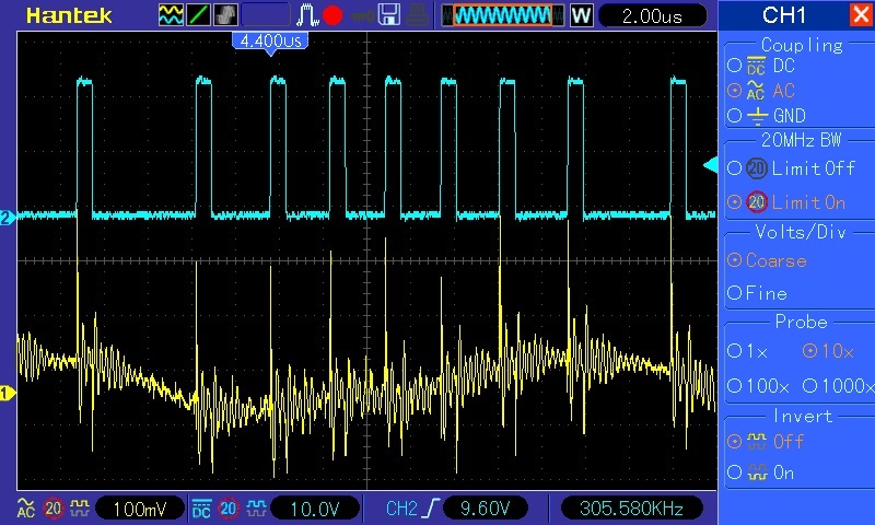
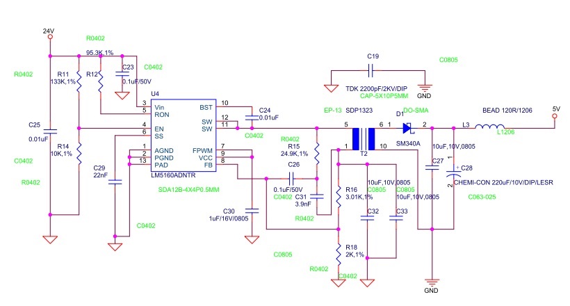
LM5160A: PWM unstable
↧
CCS/TM4C123GH6PM: hibernate mode and lab6 from TM4C123G workshop
Part Number:TM4C123GH6PM
Tool/software: Code Composer Studio
Hello,
I made a custom TM4C123 board, and I managed to program it by using another launchpad as a JTAG adapter.
In my board, there is a battery that supplies the VBAT, and I also managed to get RTC working as well.
Now i am trying to test the hibernate module. I have a wake button connected as specified.
I imported the lab6 project as specified with CCS Version: 8.0.0.00016
Here is the code I am trying to compile:
#include <stdint.h>
#include <stdbool.h>
#include "utils/ustdlib.h"
#include "inc/hw_types.h"
#include "inc/hw_memmap.h"
#include "driverlib/sysctl.h"
#include "driverlib/pin_map.h"
#include "driverlib/debug.h"
#include "driverlib/hibernate.h"
#include "driverlib/gpio.h"

int main(void)
{
    SysCtlClockSet(SYSCTL_SYSDIV_5|SYSCTL_USE_PLL|SYSCTL_XTAL_16MHZ|SYSCTL_OSC_MAIN);

    SysCtlPeripheralEnable(SYSCTL_PERIPH_GPIOF);
    GPIOPinTypeGPIOOutput(GPIO_PORTF_BASE, GPIO_PIN_1|GPIO_PIN_2|GPIO_PIN_3);
    GPIOPinWrite(GPIO_PORTF_BASE,GPIO_PIN_1|GPIO_PIN_2|GPIO_PIN_3, 0x08);

    SysCtlPeripheralEnable(SYSCTL_PERIPH_HIBERNATE);
    HibernateEnableExpClk(SysCtlClockGet());
    HibernateGPIORetentionEnable();
    SysCtlDelay(64000000);
    HibernateWakeSet(HIBERNATE_WAKE_PIN);
    GPIOPinWrite(GPIO_PORTF_BASE,GPIO_PIN_3, 0x00);

    HibernateRequest();
    while(1)
    {
    }
}
and I get this error:
**** Build of configuration Debug for project lab6 ****
"C:\\ti\\ccsv8\\utils\\bin\\gmake" -k all
Building file: "../main.c"
Invoking: ARM Compiler
"C:/ti/ccsv8/tools/compiler/ti-cgt-arm_18.1.1.LTS/bin/armcl" -mv7M4 --code_state=16 --float_support=FPv4SPD16 --abi=eabi -me --include_path="C:/ti/ccsv8/tools/compiler/ti-cgt-arm_18.1.1.LTS/include" -g --define=PART_TM4C123GH6PM --display_error_number --diag_wrap=off --diag_warning=225 --preproc_with_compile --preproc_dependency="main.d_raw" "../main.c"
>> Compilation failure
subdir_rules.mk:9: recipe for target 'main.obj' failed
"../main.c", line 3: fatal error #1965: cannot open source file "utils/ustdlib.h"
1 catastrophic error detected in the compilation of "../main.c".
Compilation terminated.
gmake: *** [main.obj] Error 1
gmake: *** No rule to make target 'C:/ti/ccsv8/eclipse/TIVAWARE_INSTALL/driverlib/ccs/Debug/driverlib.lib', needed by 'lab6.out'.
gmake: Target 'all' not remade because of errors.
**** Build Finished ****
Any ideas/help greatly appreciated,
-C.A.
↧
DRV8848: DRV8848 LED CONSTANT SINK CURRENT DRIVER CONFIGURATION
Part Number:DRV8848
Hello dear,
Can you help me with confirming which configuration will work, A or B ?
I think both configuration will do the same work, if that is the case, i would go with (A), because same current is divided on 2x FET instead of just one (on B config) .
Thanks in advance

↧
↧
CC2530: Restore configuration in another device .
↧
Linux/AM3352: Identifying boot device in u-boot
Part Number:AM3352
Tool/software: Linux
Hi,
I have a board with both SD and eMMC - MMC0 and MMC1
The boot sequence is boot from eMMC and if no success then boots from SD.
How can I know in U-BOOT from where it was booted?
Thanks
Avner
↧
CCS/F28M36P63C2: Trying to print voltage and current reading on LCD using SPI
Part Number:F28M36P63C2
Tool/software: Code Composer Studio
Hello,
Trying to print the voltage and current reading on an LCD using spi in the concerto device. The readings are floating point values that change in real time and so i have been trying to do that by using sprintf and formatting a string, then passing the formatted string as part of the SPI data transfer. But it prints junk values instead of the string. I want to know if i am using sprintf function correctly. Below is the piece of code involving the sprintf()
char stringA[17];
float Vref1,Iref1;
sprintf(stringA, "%f VDC %f A",Vref1,Iref1);
I pass stringA as an argument in the SPI transfer function. And i don't see any cogent output, just bunch of random characters with the same length as that of the string. I just want to confirm that everything else works just fine. I am able to print regular characer strings without any issue.
Problem is only with printing strings with real time float variables in them. Been using sprintf() to accomplish this but to no avail. Am i doing this incorrectly?? or is this not possible to achieve using sprintf()?? I do have the library function assumptions set to minimal sprintf() usage.
Any suggestion is greatly appreciated, thank you for your time.
Srini
↧
DRV8703-Q1: Chip becomes hot
Part Number:DRV8703-Q1
Hi!
I was using chip for half hour, moving motor back and forth and than suddenly while playing with PWM settings, DRV8703-Q1 became very hot, and start eating 0.3A on its own.
It seems SPI still works on chip and if I leave it running for 25seconds, I get over temperature warning over SPI.
What could be wrong? how can I troubleshoot? Is this chip so sensitive that some voltage spike from Vm could make it go this way :).
Also since MLCC of 10uF / 60V are quite hard to find these days (https://www.ttiinc.com/content/ttiinc/en/resources/marketeye/categories/passives/me-zogbi-20180302.html - I decided to go without them - could that be reason of failed chip?
regards
↧
↧
RTOS/TMDSICE3359: Problems making the bootloader for AM335x and flashing the
Part Number:TMDSICE3359
Tool/software: TI-RTOS
Hi,
I am trying to follow the Processor SDK Boot Guide here  .
.
I am unable to make the bootloader file. I get an error that gmake is not a valid comment. It doesn't happen while setting up the SDK.
Secondly, there is no clear instruction of where to run the make command. That detail is completely missing. It would be helpful is someone helps clear that.
Thirdly, I have tried flashing the bootloader and the application image into the sd card and also to mcspi. The code I tried was the EtherCAT slave demo. But I don't get any response from the board in the case of mcspi.
In the case of the SD card, the UART Terminal just shows that the application is executing. There is no response from the board. By response I refer to the LCD Screen activation and LED blinking on the ICE board in case of directly debugging it through CCS.
Any guidance on this would be very very beneficial.
This would help accelerate our development in the right direction.
Regards,
Keyshav
↧
Compiler/CC2640R2F: No debug folder or .out file
Part Number:CC2640R2F
Tool/software: TI C/C++ Compiler
Hi I would like to use GUI Composer Studio to make an HMI for my project I want to communicate using JTAG XDS. I have done this once before with a different project. However, this time my project does not have a
"Debug" folder or a ".out" file. The project started its life as the Project Zero for the CC2640R2 launchpad. could someone help me please?
1. why is there no debug folder or .out file
2. how to I produce this folder and file.
Regards
↧
CCS/LAUNCHXL-CC1352R1: EasyLink
Part Number:LAUNCHXL-CC1352R1
Tool/software: Code Composer Studio
I'm currently trying to have two CC1352 devices communicate to each other (More specifically, one device broadcasts a message to all its neighbors and another device picking up the message). I found the Wireless Sensor Network Example and I got it to work, but I wanted to strip it down to just the EasyLink API so I can send a simple message between two devices without the extra overhead. All I want is for one device to broadcast a single message to all its neighbors. I wrote some code and the EasyLink_init function is not working. The code begins to execute the function and it stops executing in the middle of the function and I don't know why. What is causing this issue? How can I get the EasyLink_init function to work?
↧


