↧
DRV8711: drv8711 EVM GUI
↧
EM1402EVM: Charging
Part Number:EM1402EVM
Hi Mr. Weist Jr.:
How should I interpret this diagram to understand the function of the external 12V?

Elda
↧
↧
TPD2S300: CC Protection appears to take too long
Part Number:TPD2S300
While evaluating the TPD2S300EVM and see some odd behavior that does not appear to agree with the datasheet. The cc protection does not seem to cutoff in the 100ns mentioned in the datasheet. It seems to take 20ms.
We are testing by shorting both c_cc1 and c_cc2 to vbus.

↧
CCS/AM3359: Software for SORTE Design Examples
Part Number:AM3359
Tool/software: Code Composer Studio
The document "Simple Open Real-Time Ethernet (SORTE) Device With PRU-ICSS Reference Design" states that "TI will release the software files on a public GIT tree to maintain version control. Please contact your TI representative for further information."
Where can I get the software for the SORTE Master adn SORTE Slave?
↧
BQ25703AEVM-732: Battery pack manager evaluation board
Part Number:BQ25703AEVM-732
Hi,
we are interested in an evaluation board similar to what is shown in the picture below. BQ25703AEVM was an option due to the PowerPath, voltage and current monitoring, but it does not include neither termination voltage when the battery is charged nor protection circuit, etc. Our battery is 2S 30Ah and the required charger input voltage must be in 4 V - 30V (although this is not that important since a previous buck-boost converter can be implemented as previous stage) so basically the question is,
is there any evaluation board (or a combination of them) which includes charger powerpath, protection with standalone termination, gas gauge and balancing?

↧
↧
CCS/MSP-TS430DA38: Error: Unknown Device
Part Number:MSP-TS430DA38
Tool/software: Code Composer Studio
Hi,
I have the MSP-TS430DA38 board with the MSP430G2755 MCU in the socket. The board is connected to my PC with the MSP-FET through the JTAG connector. MSP-FET does show me green when connected to my PC.
I imported an example code for ADC10 operation from Resource Explorer (msp430g2x55_adc10_01.c) just to see if things would connect properly.
I did go into target configuration and select the msp430g2755. The code builds successfully, but when I try to flash it onto the board, it would give me an error: unknown device.
Am I missing some kind of set up? Please help!
↧
Qualification certificate for reliability testing
Hello, I don't know if this is the right place to ask this but I wanted it to be as generic as possible. Please redirect me if needed.
I'm Gabriel from TEKEVER, I would like to know if you have any kind of certificate or standard of testing that ensures the environmental tests you perform are representative of every batch or somehow ensure batch to batch repeatability.
Another aspect we would like to confirm is if the component reels have parts from the same batch / lot or is there any possibility that parts from different batches are in the same reel?
Among the components from Texas Instruments we have the following: LMZ14202EXT, MSP430F438AIPZR, RM48L952DPGET, CDCLVC1104PW and ADS62P15IRGC25, however I believe this inquiry may apply to the full spectrum of your components.
This has been recently requested by our customer in order to assure reliability and proceed with our components' qualification.
Thank you very much and best regards,
↧
RM48L952: ECC detects double bit errors but won't respond to single bit errors
Part Number:RM48L952
I am trying out ECC on my device and am having some issues. I use HALCoGen to generate the ECC code and nowECC to inject errors. When I inject a double bit error, everything works as I would expect; it gets into the prefetch abort once the 64 bit chunk with the error has been loaded. If I inject only a single bit error, no correction or exception seems to happen. This picture shows the issue happening. The upper highlighted part shows the push command at the beginning of a function. nowECC modified this line to push r5 when it should not. In the lower highlighted region, you can see it does not pop r5 off which causes some issues. From the registers displayed, it looks like it detects an uncorrectable ECC error, but it looks like it may not be referring to this section in flash.
Can anyone explain why this is happening?

↧
TLK106L: TLK106L ESD issue
Part Number:TLK106L
Dear TI engineer:
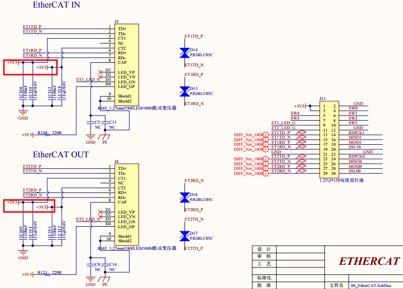
We used 2pcs TLK106L in the application of EtherCAT communication.The electrical function is OK but there is a issue when ESD test on RJ-45 Cable.
The ESD contacting voltage is 4KV and the ESD test can make the EtherCAT communication break off until the MCU reset the PHY(TLK106L).After ESD test,none of the components are broken.
The fail symptoms are on every PCB(both of 2pcs TLK106L on the same PCB).
Our schematic and PCB layout is designed according to TLK106L datasheet,the network transformer and TVS between TD+/RD+ and TD-/RD- is designed close to RJ-45 Cable.
The ESD rating of TLK106L is +/-16kV on Ethernet network pins (TD+TD-,RD+,RD-) and is too higher than the test voltage(4KV).So what is the probable reason for this issue?
Which signal should be measured by oscilloscope to help the failure analysis?
Our Schematic is below:

↧
↧
AM5KE02 SOC GEL Files
Are there and GEL files for the AM5KE02 SOC?
↧
CD4067B-MIL: Compliance with Spec
Part Number:CD4067B-MIL
Hello,
We have a customer asking if this device (CD4067BF3A) complies with spec 55-0595-37, from Grimes Aerospace. Our TI device is listed as a substitute by the customer's document, however, we do not have a mechanism to confirm.
The CD4067B was manufactured by a range of semiconductor companies, and now appears to now be only manufactured by TI.
Could someone please have a look in to this? If necessary, please feel free to contact me offline.
Thanks,
↧
CC2650MODA: Module Breakout
Part Number:CC2650MODA
Currently using CC2650MODAMOHT module in our project. we are planning to not use a module and use a chip by itself. so we needed more information on whats inside this module. components used.
↧
Compiler/PRU-SWPKG: clpru behaves differently in docker image vs ubuntu desktop; fails with "exec() error spawning acpiapru: No such file or directory"
Part Number:PRU-SWPKG
Tool/software: TI C/C++ Compiler
I'm attempting to migrate our build system to a docker image for portability, but I'm having trouble with an error from clpru. The issue arises when clpru calls out to acpiapru, which it can't find on the docker image. This process works fine on a regular ubuntu desktop, but calling the command from the docker image returns exec() error spawning acpiapru: No such file or directory.
The following strace -f results from the call to clpru may shed some light on the issue.
This one, from the Ubuntu desktop, stat64s the correct file, and later calls execve with the appropriate path and arguments.
...
stat64("/home/chrismoore/Toolchain-Release/Install/pru-cgt/bin/acpiapru", {st_mode=S_IFREG|0775, st_size=5619510, ...}) = 0
times({tms_utime=0, tms_stime=0, tms_cutime=18434949165801799680, tms_cstime=654151969196478216}) = -2066578729
clone(Process 20811 attached
child_stack=0, flags=CLONE_CHILD_CLEARTID|CLONE_CHILD_SETTID|SIGCHLD, child_tidptr=0) = 20811
[pid 20811] execve("/home/chrismoore/Toolchain-Release/Install/pru-cgt/bin/acpiapru", ["/home/chrismoore/Toolchain-Relea"..., "-@/tmp/20810rVuXUT"], [/* 31 vars */] <unfinished ...>
...
This one, from the docker image, stat64s the correct file, but then searches the path for acpiapru, and since its not on the path, it fails on this step.
...
stat64("/Toolchain-Release/Install/pru-cgt/bin/acpiapru", {st_mode=S_IFREG|0775, st_size=5619510, ...}) = 0
times({tms_utime=0, tms_stime=0, tms_cutime=18428393396440662016, tms_cstime=654398603398541216}) = 15236258
clone(child_stack=0, flags=CLONE_CHILD_CLEARTID|CLONE_CHILD_SETTID|SIGCHLD, child_tidptr=0x9144898) = 88
strace: Process 88 attached
[pid 87] wait4(-1, <unfinished ...>
[pid 88] execve("/usr/local/sbin/acpiapru", ["acpiapru", "-@/tmp/00087LfF4u0"], [/* 11 vars */]) = -1 ENOENT (No such file or directory)
[pid 88] execve("/usr/local/bin/acpiapru", ["acpiapru", "-@/tmp/00087LfF4u0"], [/* 11 vars */]) = -1 ENOENT (No such file or directory)
[pid 88] execve("/usr/sbin/acpiapru", ["acpiapru", "-@/tmp/00087LfF4u0"], [/* 11 vars */]) = -1 ENOENT (No such file or directory)
[pid 88] execve("/usr/bin/acpiapru", ["acpiapru", "-@/tmp/00087LfF4u0"], [/* 11 vars */]) = -1 ENOENT (No such file or directory)
[pid 88] execve("/sbin/acpiapru", ["acpiapru", "-@/tmp/00087LfF4u0"], [/* 11 vars */]) = -1 ENOENT (No such file or directory)
[pid 88] execve("/bin/acpiapru", ["acpiapru", "-@/tmp/00087LfF4u0"], [/* 11 vars */]) = -1 ENOENT (No such file or directory)
[pid 88] write(2, "exec() error spawning acpiapru: "..., 58exec() error spawning acpiapru: No such file or directory
) = 58
...
Is this a bug in the compiler?
↧
↧
BQ20Z45: SOCC Perm Failure after Discharge Current
Part Number:BQ20Z45
Hello,
I have a a battery where I am testing three protection tiers:
OC Dsg, 20A for 2 seconds
OC Dsg, 37A for 31mS
SC Dsg, 95A for 0 seconds
While checking the accuracy of these tiers, I setup a CC load to be 36A, which would shut down in ~2 seconds under the 1st tier. This did cutoff after 2.44 seconds as expected, but the pack would not come back on. After hooking back up to the BQ Software, there was a PF for SOCC. This failure appears to be charge current related so I am unsure how this is possible.
Thank you in advance for your help, Mike
↧
High Frequency High Voltage amplifier for piezoelectric transducers
I need to drive multiple piezoelectric transducer at high frequencies(1MHz - 8MHz), but my function generator is not able to provide high voltage(ranging from 100-250v is needed for effective vibration amplitude). I am not sure what amplifier would be suitable for these frequencies, as this seems to be quite difficult to achieve. I would appreciate it if anyone could help me figure out what amplifier would be able to provide me with what I need.
Thanks in advance.
↧
TPS68470: TPS68470 required HDI board? What is the advantage for using S_VSYNC
↧
TINA/Spice/TPS57140-Q1: TINA/Spice/TPS57140-Q1
Part Number:TPS57140-Q1
Tool/software:TINA-TI or Spice Models
I am trying to run the unencrypted SPICE model for the TPS57140-Q1. The problem I have at present is that when the model is loaded and a symbol created for it, the model will run but there are currently two issues with the model.
1) The model runs very slowly
2) The model appears not to have the correct output in that it is low.
I had to make use of the PWRGD output and the DUMMY_TEMPIN pins. I understand that the PWGD pin is an open drain output, so what would you think is appropriate here? I temporarily put a pull-up resistor to a 3.3V supply. the DUMMY_TEMPIN I put to a 20V source, on the basis this may be read as 20degC. I originally grounded both of these inputs and the model ran.
I have checked the complete circuit. I have even only chosen 1 waveform to save and graph, but still the model runs slowly or there is a 0V output. I have also tried reducing the output smoothing capacitance. Unfortunately it takes so long to run, it is not possible to check the output later and it is not possible to see if it springs into life later or not.
Can you advise what could be the problem please?
↧
↧
CC331x/CC332x
Sorry for the lengthy post.
Our application requires us to capture a 5 MP image every 10 minutes or so, and transfer it over Wifi to a local server. We are battery operated so power consumption is a key careabout.
Image Capture:
What is the approximate time to wake up from standby to full image capture?
Do you have reference firmware (drivers) to control an external camera module (eg: TDnext Omnivision 5MP camera module)
Does an external camera module directly connect to the CC3300 or need a special connector/cable to interface?
Can we get or purchase
An EVK with the CC3300 and an external camera module such as the one above, or
A CC330 reference board which you would recommend as being compatible with the camera module referenced above?
Wifi:
Can you provide some reference code for transmitting a 1.5 MB compressed file from external memory (say an SD card) over Wifi? We would like this to use a DMA transfer.
Would you recommend SD card or a flash memory for file storage. We want to store image(s) in the memory. Would you recommend flash or SD card?
Can you confirm the power numbers based on your datasheet? Based on the numbers below, which TX power should we use. We don't want to be too conservative or too optimistic.
TX power level = 0 54 OFDM, typ power = 226 mA
TX power level = 4 54 OFDM, typ power = 163 mA
TX power level = 0, 6 OFDM, typ power = 254 mA
TX power level = 4, 6 OFDM, typ power = 185 mA
Is there a power control loop in software? If so, can we get that as a reference design?
Please confirm that while the Wifi is sleep, the power consumption of the MCU is 15 mA
What is the typical wake-up routine after WiFi sleep? How long does it take?
Example:
- restablish connection,
check wifi status
Transmit
Do you recommend someone who provides design services to put this CC3300 + camera module and battery together?
↧
TPS27081A: TPS27081A is not functional
Part Number:TPS27081A
Hi ,
I am using TPS27081A in of one the designs.
When enable is low, I not getting a proper high voltage on Pin no.6,even
though my input(pin 4) is present. It is a kind of oscillating nature on Pin no.6. So even if enable (pin no.5) has low voltage the switch is conducting.
Below is the schematics:

what is wrong in this. Output is connected to the USB connector. Please suggest.
Regards,
Jenitt Maria Francis
↧
CCS/MSP430F5419A: FLASH Programming on MSP430F5419A
Part Number:MSP430F5419A
Tool/software: Code Composer Studio
Hello,
I am trying to save the status of the switch in flash programming to save the desired setting but the code didn't work, please help me.
#include <msp430.h>
unsigned int Rdata[];
unsigned int Sw[];
// Function prototypes
void read(void);
void write(void);
void switching(unsigned int);
void main(void)
{
WDTCTL = WDTPW + WDTHOLD; //Disable the Watchdog timer for convenience.
P1DIR |= BIT0; //Set pin 4.1 to the output direction.
P1DIR |= BIT1;
// P4SEL |= BIT1; //Select pin 4.1 as our PWM output
//configuring the switch
P2REN |= (BIT7 + BIT6);
P2OUT |= (BIT7 + BIT6);
P2IE |= (BIT7 + BIT6);
P2IES |= (BIT7 + BIT6);
P2IFG &= ~(BIT7 + BIT6);
__enable_interrupt();
while (1)
{
write();
unsigned int b;
unsigned int c;
if (Sw[1] == 0)
{
b = Sw[0];
switching(b);
}
else if (Sw[1] == 1)
{
read();
c = Rdata[0];
switching(c);
}
}
}
void switching(unsigned int a)
{
if (a == 0)
{
P1OUT = BIT0;
}
else if (a == 1)
{
P1OUT = BIT1;
}
}
void write(void)
{
int *Flash_ptr; // Flash pointer
unsigned int i;
Flash_ptr = (int *) 0x1000; // Initialize Flash pointer
FCTL1 = FWKEY + ERASE; // Set Erase bit
FCTL3 = FWKEY; // Clear Lock bit
*Flash_ptr = 0; // Dummy write to erase Flash segment
FCTL1 = FWKEY + WRT; // Set WRT bit for write operation
for (i = 0; i < 1; i++)
{
while ((FCTL3 & BUSY) != 0)
;
*Flash_ptr++ = Sw[i]; // Write value to flash
}
FCTL1 = FWKEY; // Clear WRT bit
FCTL3 = FWKEY + LOCK; // Set LOCK bit
}
void read(void)
{
int *Flash_ptr; // Flash pointer
unsigned int i;
Flash_ptr = (int *) 0x1000; // Initialize Flash pointer
for (i = 0; i < 1; i++)
{
while ((FCTL3 & BUSY) != 0)
;
Rdata[i] = *Flash_ptr++;
}
}
#pragma vector=PORT2_VECTOR
__interrupt
void Port_2(void)
{
switch (__even_in_range(P2IV, 0x10))
{
case 0x00:
break; //None
case 0x02:
break; //Pin0
case 0x04:
break; //Pin1
case 0x06:
break; //pin2
case 0x08:
break; //pin3
case 0x0A:
break; //pin4
case 0x0C:
break; //pin5
case 0x0E:
{
if (Sw[1] < 2)
{
Sw[1]++;
}
else
{
Sw[1] = 0;
}
P2IFG &= ~BIT6;
break;
}
case 0x10:
{
//pin7
if (Sw[0] < 2)
{
Sw[0]++;
}
else
{
Sw[0] = 0;
}
P2IFG &= ~BIT7;
break;
}
}
}
↧