Quantcast
Channel: Forums - Recent Threads
Viewing all 262198 articles
Browse latest View live

CCS/AM5728: Error connecting to the target (Error - 2062 @ 0x34BC)

$
0
0

Part Number:AM5728

Tool/software: Code Composer Studio

Hello,

this is the first time I work with a beagleBoard for a practical course and I really need your help:

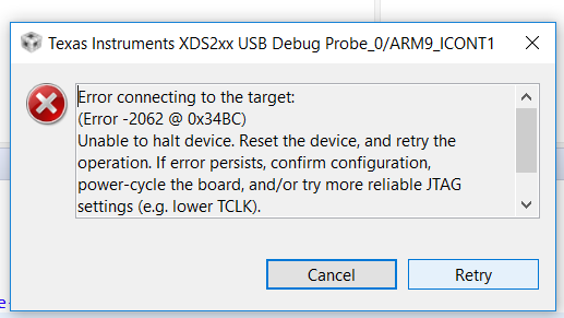
I'm using a BeagleBoard x15 and CCS Version 7.4.0.00015 and Spectrum Digitial XDS200 to run a simple program that turns on an onboard LED. The Code works, if I'm executing it on a debian image on the board. I want to test if i can execute code via CCS and I'm using this LED code. When I debug the code I get following error message:

and the console output:

Cortex_M4_IPU1_C0: GEL Output: --->>> AM572x Cortex M4 Startup Sequence In Progress... <<<---

Cortex_M4_IPU1_C0: GEL Output: --->>> AM572x Cortex M4 Startup Sequence DONE! <<<---

Cortex_M4_IPU1_C1: GEL Output: --->>> AM572x Cortex M4 Startup Sequence In Progress... <<<---

Cortex_M4_IPU1_C1: GEL Output: --->>> AM572x Cortex M4 Startup Sequence DONE! <<<---

C66xx_DSP1: GEL Output: --->>> AM572x C66x DSP Startup Sequence In Progress... <<<---

C66xx_DSP1: GEL Output: --->>> AM572x C66x DSP Startup Sequence DONE! <<<---

C66xx_DSP2: GEL Output: --->>> AM572x C66x DSP Startup Sequence In Progress... <<<---

C66xx_DSP2: GEL Output: --->>> AM572x C66x DSP Startup Sequence DONE! <<<---

CortexA15_0: GEL Output: --->>> AM572x Cortex A15 Startup Sequence In Progress... <<<---

CortexA15_0: GEL Output: --->>> AM572x Cortex A15 Startup Sequence DONE! <<<---

CortexA15_1: GEL Output: --->>> AM572x Cortex A15 Startup Sequence In Progress... <<<---

CortexA15_1: GEL Output: --->>> AM572x Cortex A15 Startup Sequence DONE! <<<---

IcePick_D: GEL Output: Ipu RTOS is released from Wait-In-Reset.

IcePick_D: GEL Output: Ipu SIMCOP is released from Wait-In-Reset.

IcePick_D: GEL Output: IVAHD C66 is released from Wait-In-Reset.

IcePick_D: GEL Output: IVAHD ICONT1 is released from Wait-In-Reset.

IcePick_D: GEL Output: IVAHD ICONT2 is released from Wait-In-Reset.

ARM9_ICONT1: Error connecting to the target: (Error -2062 @ 0x34BC) Unable to halt device. Reset the device, and retry the operation. If error persists, confirm configuration, power-cycle the board, and/or try more reliable JTAG settings (e.g. lower TCLK). (Emulation package 7.0.100.0)

I need your help, since the resolving recommandations of https://e2e.ti.com/support/development_tools/code_composer_studio/f/81/t/337413?CortexR4-Error-connecting-to-the-target-Error-2062-0x0-Unable-to-halt-device-


TIDL : Import pre-trained SSD model using caffe

$
0
0

Hi,

I have downloaded caffe-jacinto pre-trained model from below link:

https://github.com/tidsp/caffe-jacinto-models/tree/caffe-0.16/trained/object_detection/voc0712/JDetNet/ssd512x512_ds_PSP_dsFac_32_fc_0_hdDS8_1_kerMbox_3_1stHdSameOpCh_1/sparse

According to TIDeepLearningLibrary_UserGuide.pdf, I changed needed config files. And I am able to generate .bin files.

I used that .bin files to run ssd application on EVE with simulator, but it's taking too much time for execution(nearly 48 hours).

After successful execution I tried to visualize resultant bin, but I am unable to visualize with a given input image because of some wrong data in bin file.

I have attached all needed data for your reference.

Please guide me to resolve this issue.(Please visit the site to view this file)

UCD9090A: UCD9090A / Unused pin connection

$
0
0

Part Number:UCD9090A

Hi,

Please let me know the unused pin connection for following pins.

  1. MONxx (Actually MON11 is unused)
  2. GPIOxx
  3. PWM1/GPI1, PWM2/GPI2

Best Regards,

Satoshi / Japan Disty

Best Regards,

Satoshi / Japan Disty

TPS55165-Q1: Similar device with lower VIN_startup capability

$
0
0

Part Number:TPS55165-Q1

Is there a TPS55165-Q1 variant available with a startup voltage (min) of something more like 4.7V (instead of 5.3V)?  The TPS55165-Q1 is an almost perfect fit for my application (wide input voltage range, 2 MHz switching, able to provide output of 5V at 1A for a wide input voltage range), but I really need a lower startup voltage capability.  This would allow me to power the application using a 5V rail (e.g., USB) with a protection diode (Schottky).  Thanks!

Linux/AM5728: Video Stream / 2 Cameras

$
0
0

Part Number:AM5728

Tool/software: Linux

Hello together,

For a project I would like to embedd two cameras (1080p, 30FpS). The data format is 12-bit raw data.
I would like to stream camera data in MPEG-4/H.264 via USB or Ethernet to a PC.
After I read the documentation I'm not sure if the AM572x is the right choice for that project.

Has anybody some experience? Is it even possible?
Thanks a lot.

Greetings
Michael

F28M35H52C: ADC Source Impedance setup.

$
0
0

Part Number:F28M35H52C

Dear All,

I am looking for information about the way to impedance setup on the ADC input of the concerto microcontroller family (F28M35H52C).

Does the application report "SPNA118B – Septembre 2011" "ADC Source Impedance for Hercules™ ARM® Safety MCUs" can be used as a base for the choice of the capacitor and resistor on ADC inputs ?

Does this application report can also apply to the Delfino family microcontroler TMS320F29377D ?

Thank you for your help.

CC2650: E320003 : cc2650 sensortag : REV: 1.3

$
0
0

Part Number:CC2650

E320003 : CC2650 sensor tag : REV: 1.3.2

Hello,

Unable to read accelerometer sensor data from CC2650 sensor tag with raspberry pi 3. I tried to scan for UUID services using gatttool command (char-desc) it lists all the UUID for temperature(f000aa01, handle:0x0024), humidity(f000aa21, handle:0x002C), barometer sensors(ff000aa41, handle:0x0034) and so on.

Acceleration(f000aa11, handle:??) is not shown. Does my CC2650 sensor tag has any problem ?

but it works fine when its connected to smart phone app? I can see all the data on app.

what should be done to activate the sensor to read data from raspberry pi ?

Thank you

Regards:

Rajesh

TMDSLCDK6748: How to include previous samples for FIR filter DSPF_sp_fir_gen()

$
0
0

Part Number:TMDSLCDK6748

Hi all,

Can you help me figure out how to include previous samples in FIR filter. According to the TMS320C67x DSP Library Programmers Ref. Guide SPRU657C, the input array starts at x(-nh+1) and ends at x(nr-1).

To test the filter, I'm using the mcaspPlayBk.c from the StarterWare C6748_StarterWare_1_20_04_01

To construct the input array for the FIR filter, I'm increasing the buffer size from its default of 2000 samples to 2015 for a 16-tap filter. The problem I have (I think) is that I don't know how to insert (nh-1) previous samples to the head of buffer. Since the data comes in frames, I'm trying to save the last (nh-1) sample from the previous frame then using them in the "current" frame. But this isn't working.

Here is my code, which is modified version of mcaspPlayBk.c:

    while(1)
    {
        if(lastFullRxBuf != lastSentTxBuf)
        {
            /*
            ** Start the transmission from the link paramset. The param set
            ** 1 will be linked to param set at PAR_TX_START. So do not
            ** update paRAM set1.
            */
            parToSend =  PAR_TX_START + (parOffTxToSend % NUM_PAR);
            parOffTxToSend = (parOffTxToSend + 1) % NUM_PAR;
            parToLink  = PAR_TX_START + parOffTxToSend;

            lastSentTxBuf = (lastSentTxBuf + 1) % NUM_BUF;

            // is this necessary?
            memcpy(tempCharBuf, (void *)rxBufPtr[lastFullRxBuf], AUDIO_BUF_SIZE);
            /*
            **convert char array to short signed int array starting at NH
            */
            unpackMcASPBuf(tempCharBuf, NUM_SAMPLES_PER_AUDIO_BUF, NH, singleChannelInt);
            counter++; //for debugging
            /*
            ** insert previous samples to front of rx frame buffer for FIR filter
            */
            insertPrevSamples(singleChannelInt, previousSamples, NH);
            /*
            ** save trailing NH samples for next frame
            */
            saveTrailingSamples(singleChannelInt, NUM_SAMPLES_PER_AUDIO_BUF, previousSamples, NH);
            /*
            ** convert to sp float for FIR filter
            */
            intToFloat(singleChannelInt, NUM_SAMPLES_PER_AUDIO_BUF + NH, DSPInputSignal);
            /*
            **FIR filter
            */
            DSPF_sp_fir_gen(DSPInputSignal, filterCoefs, DSPOutputSignal, NH, NUM_SAMPLES_PER_AUDIO_BUF );
            /*
            ** convert back to int for txBuf
            */
            floatToInt(DSPOutputSignal, NUM_SAMPLES_PER_AUDIO_BUF, tempIntBuf);
            /*
            ** interleave back into txBuf short int to char conversion
            */
            packMcASPBuf(tempIntBuf, NUM_SAMPLES_PER_AUDIO_BUF, tempCharBuf);
            memcpy((void *)txBufPtr[lastSentTxBuf], tempCharBuf, AUDIO_BUF_SIZE);
            /*
            ** Send the buffer by setting the DMA params accordingly.
            ** Here the buffer to send and number of samples are passed as
            ** parameters. This is important, if only transmit section
            ** is to be used.
            */
            BufferTxDMAActivate(lastSentTxBuf, NUM_SAMPLES_PER_AUDIO_BUF,
      }
}

The functions are:

void insertPrevSamples(short signed int* x, short signed int* p, int np){ //p = previous
        int i=0;
        for(i= 0; i < np - 1 ; ++i)
                x[i] = p[i];
}

void saveTrailingSamples(short signed int* x, int nx, short signed int* p, int np){ //p = previous
        int i=0;
        for(i= 0; i < np - 1; i++)
                p[i] = x[nx + i];
}
void unpackMcASPBuf(unsigned char* x, int nx, int nh, short signed int* y){
    int i=0;
    int indx=0;
    for(i = nh; i < nx + nh; i++){
        y[i]  = x[indx+1] << 8;
        y[i] |= x[indx+0] << 0;
        indx += 8;
    }
}
void packMcASPBuf(short int* in, int size, unsigned char* out){
    int i=0;
    int indx=0;
    int byte0;
    int byte1;
    int byte4;
    int byte5;

    for(i=0; i< size/2; i++){
        out[indx+2] = 0;
        out[indx+3] = 0;
        out[indx+6] = 0;
        out[indx+7] = 0;

        byte0 = ( in[i] >> 0 );
        byte1 = ( in[i] >> 8 );
        byte4 = ( in[i] >> 16 );
        byte5 = ( in[i] >> 24 );

        out[indx+0] = (char)byte0;
        out[indx+1] = (char)byte1;

        out[indx+4] = (char)byte4;
        out[indx+5] = (char)byte5;
        indx += 8;
    }
}

Also included is a waveform showing the corrupted nh-1 samples at the head of the buffer. 

I hope this makes sense and sorry for the lengthy explanation and code.

thank you,

Scott


CCS/66AK2H14: Hyperlink is not working in non loopback mode

$
0
0

Part Number:66AK2H14

Tool/software: Code Composer Studio

Hi,

We have designed  customized  board  using 66AK2H14. We are using CCSV7.4,processor_sdk_rtos_k2hk_4_03_00_05 and TI XDS 110 debug probe to connect board to CCS.

In our board we have 3 processor ,out of which 1 is configured as Centralized Processor (Called CP henceforth) and 2 Distributing Processors (Called DP henceforth). we need to send data from DP to CP through hyperlink .

I run the memoryMapped hyperlink example by commenting #define hyplnk_EXAMPLE_LOOPBACK in ti/drv/hyplnk/example/common/hyplnkLLDCfg.h.

Version #: 0x02010007; string HYPLNK LLD Revision: 02.01.00.07:May 25 2018:11:00:09
About to do system setup (PLL, PSC, and DDR)
Constructed SERDES configs: PLL=0x00000228; RX=0x0046c495; TX=0x000ccf95
system setup worked
About to set up HyperLink Peripheral
============================Hyperlink Testing Port 0
========================================== begin registers before initialization ===========
Revision register contents:
  Raw    = 0x4e902101
Status register contents:
  Raw        = 0x00003004
Link status register contents:
  Raw       = 0x00000000
Control register contents:
  Raw             = 0x00000000
Control register contents:
  Raw        = 0x00000000
============== end registers before initialization ===========

Hyperlink Serdes Common Init Complete
Invalid Serdes Lane Enable Init 4


Q1. only commenting #define hyplnk_EXAMPLE_LOOPBACK is enough to run the code between 2 boards[In our case 2 66AK2H14 processor]?

Regards,

Mahima shanbag

BQ40Z60: Charging current too high

$
0
0

Part Number:BQ40Z60

I have custom charger design, based on BQ40Z60 evaluation board, with changes:

- without all U1 protection circuit

- without precharge circuit: F1, Q7, C10, R18, R22

- AFEFUSE pin tied to GND

- R14 changed to 1K (we have high voltage drop on ACP pin after charge was enabled)

- C18, C20, C24, C25, C27 changed to 4,7uF/25V

- no Q10-Q13 led circuit

- voltage divider: R21 = 330k, sum of R26-R29 = 24k

- BQ40Z60 firmware: bq40z60_v0_15_build_21

- connected cells: 4x parallel NCR18650GA-Panasonic with thermistor and cables for balancer

We have problem witch charging currents mismatch. BQ studio is reporting charging current to 1794mA, but for cell1-4 show about 1940mA. But to the cells is going about 2300mA (we connected 0.01R to +V4 cell, and measure voltage drop).

All voltages are calibrated and reported properly.

When I want to calibrate current (using that add-on 0.01Rfor metering), CC Gain, and Capacity Gain drops to 4.324. And all reported currents got messed up.

But sometimes I have "good" board, charging current 1794mA is almost the same as cell1-4 currents, but physically it delivers to battery about 2000mA. It works on the same golden image as other boards, only voltage calibration was done before metering.

How to fix that?

(Please visit the site to view this file)

CCS/TMS320F28379D: Can't start Compensation Designer

$
0
0

Part Number:TMS320F28379D

Tool/software: Code Composer Studio

Hi,

I can't start new version of Compensation Designer GUI. Older version (1.10.0.0) runs correctly, but version 2 isn't working.

After trying to run I get Exception Error 0xE0434352 at address 0x00007FF8A9974008. There also can't run with administrative privileges and with other Windows simulation (7, 8, XP)

I have Windows 10 64bit with 4.7.2 .net.

HD3SS3415: hd3ss3415 reference schematic

TUSB3410: Drivers not working on Win10

$
0
0

Part Number:TUSB3410

Hello, i disabled the windows signing function, instaled the latest "sllc428a" and then the TUSB3410 driver. My device with the TI chip is not recognized. The window above shows if i try to update driver via device manager. Could you help me please?

Best regards

Jaroslav

SIMPLELINK-MSP432-SDK: Simple Link DriverLib SPI Interrupt Flags

$
0
0

Part Number:SIMPLELINK-MSP432-SDK

I have code that was getting optimized out because I believe there is a macro definition issue in the MSP432 SimpleLink DriverLib.

I'm using : simplelink_msp432p4_sdk_2_10_00_14

I get the interrupt flags from SPI_getEnabledInterruptStatus

//*****************************************************************************
//
//! Gets the current SPI interrupt status masked with the enabled interrupts.
//! This function is useful to call in ISRs to get a list of pending
//! interrupts that are actually enabled and could have caused
//! the ISR.
//!
//! \param moduleInstance is the instance of the eUSCI A/B module. Valid
//! parameters vary from part to part, but can include:
//!         - \b EUSCI_A0_BASE
//!         - \b EUSCI_A1_BASE
//!         - \b EUSCI_A2_BASE
//!         - \b EUSCI_A3_BASE
//!         - \b EUSCI_B0_BASE
//!         - \b EUSCI_B1_BASE
//!         - \b EUSCI_B2_BASE
//!         - \b EUSCI_B3_BASE
//!
//! Modified registers are \b UCAxIFG.
//!
//! \return The current interrupt status as the mask of the set flags
//! Mask parameter can be either any of the following selection:
//! - \b EUSCI_SPI_RECEIVE_INTERRUPT -Receive interrupt
//! - \b EUSCI_SPI_TRANSMIT_INTERRUPT - Transmit interrupt
//
//*****************************************************************************
extern uint_fast8_t SPI_getEnabledInterruptStatus(uint32_t moduleInstance);

Note in the comment refers to (EUSCI_SPI_RECEIVE_INTERRUPT and EUSCI_SPI_TRANSMIT_INTERRUPT). 

These mask macros are also used by:

  • SPI_getInterruptStatus
  • SPI_disableInterrupt
  • SPI_enableInterrupt

When i look at how the macros are defined you get the following in (ti/simplelink_msp432p4_sdk_2_10_00_14/source/ti/devices/msp432p4xx/driverlib/spi.h)

#define EUSCI_SPI_TRANSMIT_INTERRUPT    EUSCI_B_IE_TXIE_OFS
#define EUSCI_SPI_RECEIVE_INTERRUPT     EUSCI_B_IE_RXIE_OFS

Now the concern is  EUSCI_B_IE_TXIE_OFS and EUSCI_B_IE_RXIE_OFS refer to bitmap offsets rather than the bitmap value.  This can be seen in: (ti/simplelink_msp432p4_sdk_2_10_00_14/source/ti/devices/msp432p4xx/inc)

/* EUSCI_B_IE[RXIE] Bits */
#define EUSCI_B_IE_RXIE_OFS                      ( 0)                            /*!< UCRXIE Bit Offset */
#define EUSCI_B_IE_RXIE                          ((uint16_t)0x0001)              /*!< Receive interrupt enable */
/* EUSCI_B_IE[TXIE] Bits */
#define EUSCI_B_IE_TXIE_OFS                      ( 1)                            /*!< UCTXIE Bit Offset */
#define EUSCI_B_IE_TXIE                          ((uint16_t)0x0002)              /*!< Transmit interrupt enable */

Note that EUSCI_B_IE_RXIE_OFS which defines EUSCI_SPI_RECEIVE_INTERRUPT is 0, so any mask checks against it, will always fail.  So the code below was always getting optimized out.  

   if( flags & EUSCI_SPI_RECEIVE_INTERRUPT )
   {
      /* USCI_B0 TX buffer ready? */
      while (!(SPI_getInterruptStatus(pCtxt->module, EUSCI_B_SPI_TRANSMIT_INTERRUPT)));

      rxData = SPI_receiveData(pCtxt->module);

I can correct this using my own definition for the interrupt mask bits. 

However I would like to know if  am I misunderstanding the comments about the "mask" macros, or is there a bug in the macro definition?

Or the other possibility did I accidentally copy/paste over the macro when digging into the header files for the macros?

TDC1011: TDC1000 vs TDC1011

$
0
0

Part Number:TDC1011

What are the differences between these devices?   I am am looking through the datasheets and they appear to be very similar.


SIMPLELINK-CC2640R2-SDK: v1.50 Simple Peripheral services even if it is commented out at code?

$
0
0

Part Number:SIMPLELINK-CC2640R2-SDK

Hi,

    I commented out the simple peripheral services below, but I can still see the services at LightBlue App, why?

// Initialize GATT attributes
  GGS_AddService(GATT_ALL_SERVICES);           // GAP GATT Service
  GATTServApp_AddService(GATT_ALL_SERVICES);   // GATT Service
  //DevInfo_AddService();                        // Device Information Service
  //SimpleProfile_AddService(GATT_ALL_SERVICES); // Simple GATT Profile

-kel

LM117HVQML-SP: Mass: Missing Value

Compiler/TM4C1290NCPDT: How to set up an interrupt timer on the TM4C1290NCPDT

$
0
0

Part Number:TM4C1290NCPDT

Tool/software: TI C/C++ Compiler

All,

I'm trying to set up an interrupt service routine that gets triggered every 2 seconds. On my most processors I have worked, even TI, we could set up an interrupt service routine that does just that, I want to be able to stop, start and restart this interrupt service routine. On the TM4C1290NCPDT, it is not readily apparent to me how to do. There are 7 timers. Timer 1, 2, 3, 4, 7 are already used. When I try to use timer 5, the code somehow hangs. But I believe this should be straightforward, how to set up a timer interrupt.

Any ideas

TPS2662: TPS26623 Availability

$
0
0

Part Number:TPS2662

Hi,

We want to use the TPS26623 in a range of products. But without a clue about part availability, this is a bit tricky...

When can we expect this part to be available for purchase, either via TI store or via Digikey/Mouser?

Thanks, Henk

WEBENCH® Tools/LM27403: Error when sharing designs

$
0
0

Part Number:LM27403

Tool/software: WEBENCH® Design Tools

Hi,

I created and shared with the share tool in webench several designs, including one with the LM27403, with both myself and one other. Both of us, when trying to access the shared designs get a server error: "This server has encountered an internal error which prevents it from fulfilling your request. The most likely cause is a misconfiguration. Please ask the administrator to look for messages in the server's error log."

The ID of the design using the LM27403 is 208045.

Viewing all 262198 articles
Browse latest View live


<script src="https://jsc.adskeeper.com/r/s/rssing.com.1596347.js" async> </script>