Quantcast
Channel: Forums - Recent Threads
Viewing all 262198 articles
Browse latest View live

TLV62568: Design feasibility

$
0
0

Part Number:TLV62568

Hello,

I have a Li-ion 18650 cell battery pack of 1s5p configuration. I am employing a Boost converter (TPS61089) to obtain Vout=5V @Iload=2A.

I am supplying three loads with the boost converter output. on of them is a step-down converter TLV62568 taking input supply from TPS61089 and

giving an output of Vout=3.3V @Iload=1A, I am powering a MPS432P401 with the output of buck converter. This is the block diagram;


My questions are;

Q1. Will I encounter any noise in the supply given to MSP432 by TLV62568? If yes then what type of precaution I need to consider?

Q2. Does the noise from a converter affect the normal operation of MSP432?

Q3. Will the output of TPS61089 be noise free? If not what precautions I need to consider?

Q4. Is there a possibility of noise entry from boost converter TPS61089? Any specific measures that I need to consider?

Thanks and regards

Swaroop


ADS127L01EVM: Connection problems

$
0
0

Part Number:ADS127L01EVM

First I want to say sorry because I know it is basic questions, but my major is not electronics then I have some trouble.
1) Is it possible to connect 2 analog inputs at the same time? because I saw 2 SMA jacks, or we must use 2 jacks for 1 input?
2) How can I connect it if my input come from photodetector with 1 bnc connector?
Thanks you for your attention!

CC2540EMK-USB: USB Device Not Recognized after Programming

$
0
0

Part Number:CC2540EMK-USB

Hi team,

I am using the CC-DEBUGGER to program my CC2540EMK-USB so I can use it as a BLE packet sniffer. Here are the steps that I am running:

  1. Connect CC-DEBUGGER to PC via miniUSB cable
  2. Connect CC-DEBUGGER to CC2540EMK-USB
  3. Plug CC2540EMK-USB into PC (for power)
  4. Press reset on CC-DEBUGGER
  5. Flash sniffer_fw_cc2540.hex found here: C:\Program Files (x86)\Texas Instruments\SmartRF Tools\Packet Sniffer\bin\general\firmware using Flash Programmer tool (Erase, program and verify)

Immediately after step 5 is done, I am getting an error from Windows saying that "USB Device Not Recognized" and that "One of the USB devices attached to this computer has malfunctioned.." Any idea what might be wrong? After unplugging and plugging back in the CC2540EMK-USB with the CC-DEBUGGER removed, I'm still getting the error and nothing is detected in my PACKET-SNIFFER tool.

Regards,

Akash Patel

RTOS/CC3220: SSL certificate update issue

$
0
0

Part Number:CC3220

Tool/software:TI-RTOS

Hi

We are using CC3220 controller and we have implemented OTA for this micro controller  and able to upgrade mcu image in sys folder of ota package of uniflash.

We have 2 doubts regarding SSL CERTIFICATE or service packs


1. If ssl certificate gets expired then how can we check this & make it working?

2. Is there is any provision to update certificates from ota process?
If yes then can you guide for this?


We are using Sdk: 2.10.00.04

AMC1306E25: Modulator clock - artefacts caused by heating up.

$
0
0

Part Number:AMC1306E25

Recommended Modulator Clock

Evaluating AMC1306 (first prototype series) - we see some problems concerning stability of this part.

Running with somewhat 16MHz on CLKIN - we see artefacts on heating up the device.

Isolating the problem - without thermal treatment - it looks like there are some modulator clock ranges/frequencies which introduce artefacts.

Is it possibly that this is introduced by beat frequencies with the internal spread spectrum oscillator for the isolation barrier ?

Are there recommended modulator clock frequencies ?

Whats the typical isolator internal clock ? Are they synced ? 

rgds.

Wolfgang

OPT3101EVM: Latte GUI do not open

$
0
0

Part Number:OPT3101EVM

Hi everyone,

I'm trying to run the GUI (latte) for the OPT 3101 EVM on my computer; however, after I double click the Latte (software) icon, a command window will open and run briefly for less than a second and then closes. and that's the end of the launch. No GUI window popped up after it.

Thank you in advance for the help.

regards,

zhengguo sun

AM3357: MT47H256M8 DDR Replacement for EVM Baseboard

$
0
0

Part Number:AM3357

Hi team,


I'm looking for a recommended replacement for MT47H256M8. This DDR chip is currently used on the AM3357 EVM Baseboard, but it is EOL'd.

Are there any DDR chips you'd recommend in its place?

Thanks,

Brian Angiel

CONNECT WITH AN ENGINEER FROM TI

$
0
0

Hello, I'm with TruClear Global and our lab has developed a Nano Mechanical Application called TruOpaque that greatly enhances gain in rear projection.  We think it would or could greatly enhance rear projection DLP.  Would it be possible to talk Engineer to Engineer to set up a demo from our laboratory at TruClear Global, Newport Beach California some time in the close future? 


AICPUREPATH_STUDIO: Request For Software

$
0
0

Part Number: AICPUREPATH_STUDIO

I have not received a response to my request for PurePath Studio.  I believe my request was submitted on 4/16/2018.  The email address used is the following: ryan@visionmetering.com

CC2540: CC2540 USB Dongle Windows 10 x64 Driver

$
0
0

Part Number:CC2540

We have purchased a CC2541 Mini Development Kit, and I have connected the CC2540 dongle to my laptop running Windows 10. BTool is able to see the device and use it to connect to our keyfob.

My problem is that Packet Sniffer doesn’t detect the device, and the “Select capturing device” window shows no devices. I tried burning the flash, but SmartRF Flash Programmer also doesn’t see my CC2540.

My device is showing up as a COM port:

Per instructions that I found here:

     e2e.ti.com/.../675209

I installed SmartRF Tools and tried to update the driver with what is in this folder:

     C:\Program Files (x86)\Texas Instruments\SmartRF Tools\Drivers\cebal\win_64bit_x64

But Windows is saying that the best driver for this device is already installed, and it won't let me update the driver.

What am I doing wrong?

I am running Flash Programmer 1.12.8 and Packet Sniffer 2.18.1

Thanks,

Aram

SN74LVC8T245: max data rate

$
0
0

Part Number:SN74LVC8T245

Hi Team,

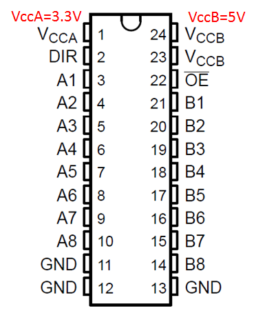
I can see the SN74LVC8T245 MAX data rate from our parametric search page, is it true this device can run up to 100Mhz at both A to B and B to A direction?

From my understand, max data rate can change according to loading and supply voltage, what is the general rule to support highest data rate?, in any specific voltage range for VccA  and VccB?

If SN74LVC8T245 has R/C loading like picture below, and VccA = 3.3V, VccB = 5V, customer wants to know the highest data rate this device support to from A to B direction. If we don't know, at least let us know, if 50MHz is no problem to support, thanks.

Regards,

Andrew

LMG3410: Demo board and cost for LMG3410

$
0
0

Part Number:LMG3410

I am searching for a demo board for the LMG3410 600 Vdc GaN FET.

Where are the boards located?

What is the cost for a board?

Compiler/CC2540: pairing fails when iOS is peripheral and CC2540 acts as central

$
0
0

Part Number:CC2540

Tool/software: TI C/C++ Compiler

Hello,

I have a pairing/bonding issue with iOS peripheral when CC2540 acts as central. I am using BLE Stack 1.4.2 on CC2540 USB Dongle. I have customized the BLECentral example in order to discover my own device and services.


I need to pair and bond the iOS peripheral without a passkey and I mus have the auto-reconnect if the devices get disconnected.

I am using the following settings.


#define PAIRING_MODE     GAPBOND_PAIRING_MODE_INITIATE

#define MITM_MODE                     FALSE

#define BONDING_MODE                  TRUE

#define IO_CAPABILITIES              GAPBOND_IO_CAP_NO_INPUT_NO_OUTPUT


On the iOS side, my own services/characteristics are not encrypted, however, I believe the Battery Service is encrypted and cannot be changed.


According to the attached snapshot taken from TI Packet Sniffer, the pairing fails with message “SM_Pairing_Failed” issued from the peripheral. Every time a pairing dialogue pops up on the iPhone, however, my device is added to the iPhone’s pairing list. I have absolutely no problem with Android and pairing/bonding/auto-reconnect work well.


I also tested the PAIRING_MODE  to GAPBOND_PAIRING_MODE_NO_PAIRING case. I will not have the bonding, hence, auto-reconnect. 

Any help's appreciated. 

Thanks

RTOS/TM4C1294KCPDT: How to create a TI-RTOS project for TM4C devices not in dev kits

$
0
0

Part Number:TM4C1294KCPDT

Tool/software:TI-RTOS

I only see TI-RTOS project templates for TM4C chips used in dev kits. In the past, I have made projects for TM4C129XNCZAD which just so happens to be used in a dev kit. I had the following option: 

Now, I want to make a project for a TM4C1294KCPDT, and there is no such option. Others have posted images where "SYS/BIOS' was an expandable category in place of "TI-RTOS Examples".

All introductory documentation I have found skip this step by building off existing projects.

TPS92210: Doesn't work in Full Range

$
0
0

Part Number:TPS92210

Hi, i was trying to do a power supply (12V@0,5A) with a Buck Configuration.

But here is the issue:  Doesn't work when my input is equal to 220V. At 127V works ok.

There is a trouble with DZ3, the voltage never reachs to 5v1, then Vref can't go to 2.5V.

the schematics is attached(Please visit the site to view this file).


MSP432P401R: GPIO INTERRUPTION: "GPIO_CFG_IN_INT_BOTH_EDGES"

$
0
0

Part Number:MSP432P401R

Hi,

I have configured one input like "GPIO_CFG_IN_INT_BOTH_EDGES" to capture how long is a input pulse (echo from HCSR04).

I have noticed with this configuration only I can detect falling edged but not the rising edge. If I configure line "GPIO_CFG_IN_INT_RISING" my code capture rising edge without problem and if I configure "GPIO_CFG_IN_INT_FALLING" my callback function capture the falling edge. Any clue about this issue?

Best regards,

My callback function code:

void hcsr04IntCallBack(uint_least8_t index){


    //Detect  rising
    if (GPIO_read(Board_GPIO_ECHO)==1){
        queueDebugSendFromISR("[HC-SR04] Echo start ++");
        startTime=xTaskGetTickCountFromISR();

    }
    // Detect failing
    else if (GPIO_read(Board_GPIO_ECHO)==0){
        queueDebugSendFromISR("[HC-SR04] Echo end --");
        GPIO_disableInt(Board_GPIO_ECHO);
        endTime=xTaskGetTickCountFromISR();
        }

    }

LM3509: Thermal and power dissipation information

$
0
0

Part Number:LM3509

Hi,

Customer is requesting the θJC, ψJT and the power dissipation information for the LM3509. Please help.

Best regards, 

Randy Chen

CCS/MSP430F5529: SPI USCIBO high frequency problem

$
0
0

Part Number:MSP430F5529

Tool/software: Code Composer Studio

Hello,
I want to setup a fast SPI-communication from a MSP430F5529 to a Display. I am using a libary to control the display, but I have to setup a SPI-protocol for faster transmittion.

The libary has four function (for the transfer), which are called up in this order:

  1. U8X8_MSG_BYTE_INIT
  2. U8X8_MSG_BYTE_START_TRANSFER
  3. Any mix of U8X8_MSG_BYTE_SEND and U8X8_MSG_BYTE_SET_DC
  4. U8X8_MSG_BYTE_END_TRANSFER

U8X8_MSG_BYTE_INIT is for the initialisation of the SPI. The U8X8_MSG_BYTE_SEND  function is for the transmition of the data. I need to send arg_int bytes, because arg_ptr will point to a buffer of size arg_int. The Chip-Select/Slave-Select is handeld in U8X8_MSG_BYTE_START_TRANSFER and U8X8_MSG_BYTE_END_TRANSFER, so I don't have to deal with it.

The two statements I have to replace in the template:

case U8X8_MSG_BYTE_SEND:
        data = (uint8_t *)arg_ptr;
        while( arg_int > 0 )
                  {
                    while (!(UCB0IFG&UCTXIFG));             // USCI_B0 TX buffer ready?
                    UCB0TXBUF = *data;
                    while (UCB0STAT & UCBUSY);
                    arg_int--;
                    data++;
                  }
break;
case U8X8_MSG_BYTE_INIT:
        P3SEL |= BIT0+BIT1+BIT2;                            // P3.0,1,2 option select MOSI MISO CLK
        UCB0CTL1 |= UCSWRST;                                // **Put state machine in reset**
        UCB0CTL0 |= UCMST+UCMSB+UCSYNC+UCCKPL;              // 3-pin, 8-bit SPI master
                                                            // MSB
        UCB0CTL1 |= UCSSEL_2;                               // SMCLK Clock Auswahl
        UCB0BR0 = 140;                                      // Baudrate 13Mhz
        UCB0BR1 = 0;                                        // The clock frequency is scaled by UCB0BR0 + UCB0BR1 * 256
        UCB0CTL0 &= ~UCCKPH;                                // Clock phase
        //UCB0CTL0 &= ~UCCKPL;
        //UCB0CTL0 &= ~UC7BIT;
        UCB0CTL1 &= ~UCSWRST;
        break;

The problem I have is, that the transmittion only works fine with a frequency up to 10kHz. If I raise the frequency it doesn't transmit correctly. Isn't it possible to have a faster SPI transmittion without interrupts? Thanks

SN65LVDM31: Dimensions

$
0
0

Part Number:SN65LVDM31

What are the dimensions for the SN65LVDM31DR? 

The datasheet located in the product folder shows the pin out but does not seem to contain the dimensions. 

WL1837MOD: TDK vs TI Module Identification

$
0
0

Part Number:WL1837MOD

Customer is migrating from TDK to TI WL1837MOD.  Is there any way for the host MPU to identify TDK vs TI module used in system?  I don't think so, but wanted to double check.

Please advise.

Thanks,
Mark

Viewing all 262198 articles
Browse latest View live