Hi:
We want to give an eMMC on the custom board as topic, how do i do?? and I have some questions list below:
(1)If our new custom board have no SD Card interface, how do i program my u-boot and kernel to eMMC(If it is worked on the custom board) ??
Hi:
We want to give an eMMC on the custom board as topic, how do i do?? and I have some questions list below:
(1)If our new custom board have no SD Card interface, how do i program my u-boot and kernel to eMMC(If it is worked on the custom board) ??
Hi,
What is the typical/peak current/power consumption for the CC3200 evaluation board? I can't seem to find any info on this in the documents.
Hi all, I am using a MicroSD card to boot the lightcrafter but failed to do so.
Below is the procedure when I was flash the firmware into SD using ubuntu.


And below is the message prompted on Hyperterminal.

By the way, the SD card is a 2G standard MicroSD card.
Thanks in advance
Martin
Hello, all
Now we have one inquiry regarding starting up output on TXB0304 from our customer.
Please refer to the item below, and feedback us with your comment.
We found one pulse on B-Port when starting up this device.
The detailed configuration of this device is as below;
A-PortA: 1.8V
B-PortB: 3.3V (This port is starting up 3ms earlier than A-Port)
During this 3ms, we found 1ms pulse on B-Port, if this port is Hi-Z or Pulldown.
As solution of this issue, we tried to have B-Port to Pulldown or OE signal to HIGH after 1.8V was established. However, there still found the pulse.
For your reference, please see the device configuration below;
(Please visit the site to view this file)
Please let us clarify how we could resolve this issue.
We thank you in advance for your information.
Best regards,
Hi,I try to change an obsai 2x rate loopback to 4x rate loopback, but it cannot work well. can you give me an example of obsai 4x rate ? thank you!
I was able to get the sd_card_m3 example working on the F28M35 ControlCard. The example demonstrations reading an SD card using the FatFS library. I was disappointed that the example does not demonstrate writes. When I tried to execute a write command the program breaks to FaultISR. Since there was no writes in the example, I am inclined to believe that pins were not configured completely or that TI did not fully port the processor to work with FatFS. The library is very straight forward, only three lines of code were needed to create a new file, as shown at the bottom. Very little information was on the forum about using the SD card reader on the F28M35 ControlCard. My expectation is that the example would be preconfigured for writing and reading -- I would like to get some feedback from others before I start digging deeper. Thanks for the help.
FIL fil; // File object
fresult = f_open(&fil, "message.txt", FA_CREATE_ALWAYS | FA_WRITE);
f_close(&fil)
Hi,
I am currently working on customer's AM335x board. On this board, SD card slot is connected to mmc0 and emmc is connected to mmc1. Recently customer is thinking to test the performance of a TI's WLink8 wifi module. Since the WLink8 is a device uses SDIO for communication. They are think to boot up the system over emmc (mmc1) and use SD card (mmc0) for wifi module. To do so, they have manage to get a SD card converter for the WLink8 module as picture below:

The software is based on SDK 07.00.00.
We have made some changes to the device trees to try to enable wifi on mmc0. But, the problem is that the wifi device is not been recognized through the SD card slot.
Is there some configuration in Linux that I am missing in order to accomplished this task?
If any one as any previous experience on enabling WLink8 on mmc0, please kindly share it with me.
Appreciate any help you could provide. Thanks in advance.
From Joseph Lee.
Q1: snipped from datasheet

what's the Class 0.1 performance?
what's the exact definition of Dynamic Range?
Q2: Why THD is larger than SFDR?
Test Condition: 80 Hz, 4 Vpp, Sine -- 8000 SPS

Look forward to your reply, thanks a million!
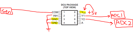
as pspice model is not available for SN74LVC2G53. i want to use it in my circuit. Biasing the IC under 5V vcc and Gnd. sensor is attached to the COM pin of demux and Y1, Y2 are connected to different ADC. IHN pin is hardwired to GND and A(pin 5) can be high or low. now my question is do i need some thing else to interface or just this setup is enough? signal from sensor can be of 1kHz with 10m to 5 volts.
I want to use RI-R6C-001A along with Tag-it HF Sandard Transponders inlays.Does anybody has an example software? I cannot undersand how to implement the tag-it transponder protocol in software.I need some starting guidance.
Hi everyone,
I am trying to do current measurements with the SensorTag connected to the CC2540 USB dongle and running BLE Device Monitor.
I can see how the period between pakets change when I change the min./max. connection interval.
When I set the slave latency to any value, nothing changes. With an interval of eg. 20ms and slave latency of 4, I can still see the current consumption every 20ms. All Sensors are off, so there should not be any data that needs transmitting...
Is anyone else having this problem? Or does the default SensorTag software not support slave latency?
Best regards
Henrik
Hi Team,
My customer is designing on AM3352, the SDK version they are using is EZSDK 06.00.00.00. They found timer 5 & 6 are used in CPSW driver(CPSW_RX_TIMER_REQ, CPSW_TX_TIMER_REQ in CPSW.c), what customer already use as PWM output. But Ethernet can’t work properly if they use timer 0 & 3 to replace or disable timer directly. I can reproduce this issue on EVM, AM335x can’t get IP address successfully once I change/disable timers.
I found it is just a workaround for PG1.0 as errata mentioned, customer is now changing to PG2.0. So could you let me know,
1. Is there a patch to disable timers in ethernet drivers?
2. Or how to change to use Timer 0 & 3 to replace?
Thank you.
I chose TPS53515 for my project and ran Webench. And I found something weird about MODE, PGOOD, VREF, and RF pins in the Webench result.
Creg is connected to PGOOD, not VREG. Voltage divider network on RF pin is connected to PGOOD. (In other words, 100kOhm is added to RFh.) I guess PGOOD and VREG is swapped. But seeing MODE pin, it is connected PGOOD and Rmode is 150kOhm, seems to implment FCCM after PGGOD high.
So I think PGOOD and VREG pin is mistakenly swapped, and MODE pin should be connected to PGOOD with Rmode.
Can anyone check and confirm this?
Dear Sir,
i have installed Cc3200 SDK 1.0 and found many example code, now I want to implement a GPIO ISR into "Out of Box" code, objective is drive cc3200 entry smart configuration mode by a GPIO, but I cannot found a GPIO Interrupt example code in the SDK, any advise?
BR
Edwin
Hi all,
I wonder if CC2530 can support multiple zigbee profiles at the same time. Such as zigbee home automation, zigbee light link.
ZHA & ZLL are both based on z-stack, what should be noticed if they work at the same time?
Regards,
Eric
I have some old (10+ yrs) code that seems to have a problem with changes in the environment around it. Problems now occur when some stray network traffic is received (memory corruption - maybe buffer overruns).
The code runs on a 6412, with 'BIOS' 4.9 and CGT 5.1.9.
While I can block the traffic causing the problem in this case I would like to fix the code.
It is the typical sort of code that runs thru a chain of descriptions when it gets an EMAC irq (via dispatcher). I was hoping for an example from the era so I can compare to see if that helps me spot some sanity checking that is missed?
Hi,
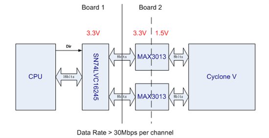
I have some quesions and hope to get your help.I am now designing board 2 which will work with board 1.Because the level question, I choose Max3013(MAXIM) for level conversion on board 2. But I am not sure whether the data path can work properly? and if there are other better solutions?
I really hope to get your help.
Thanks.
Hello,
I have a CC3200 kit, I have installed the code composer and now trying to run getting_started_with_wlan_station example.
I get the following errors:
undefined first referenced
symbol in file
--------- ----------------
ti_sysbios_BIOS_start__E C:/ti/CC3200SDK/cc3200-sdk/oslib/ccs/ti_rtos/ti_rtos.a<osi_tirtos.obj>
ti_sysbios_family_arm_m3_Hwi_Params__init__S C:/ti/CC3200SDK/cc3200-sdk/oslib/ccs/ti_rtos/ti_rtos.a<osi_tirtos.obj>
ti_sysbios_family_arm_m3_Hwi_create C:/ti/CC3200SDK/cc3200-sdk/oslib/ccs/ti_rtos/ti_rtos.a<osi_tirtos.obj>
ti_sysbios_family_arm_m3_Hwi_delete C:/ti/CC3200SDK/cc3200-sdk/oslib/ccs/ti_rtos/ti_rtos.a<osi_tirtos.obj>
ti_sysbios_family_arm_m3_Hwi_disableFxn__E C:/ti/CC3200SDK/cc3200-sdk/oslib/ccs/ti_rtos/ti_rtos.a<osi_tirtos.obj>
ti_sysbios_family_arm_m3_Hwi_getHandle__E C:/ti/CC3200SDK/cc3200-sdk/oslib/ccs/ti_rtos/ti_rtos.a<osi_tirtos.obj>
ti_sysbios_family_arm_m3_Hwi_restoreFxn__E C:/ti/CC3200SDK/cc3200-sdk/oslib/ccs/ti_rtos/ti_rtos.a<osi_tirtos.obj>
ti_sysbios_family_arm_m3_Hwi_setPriority__E C:/ti/CC3200SDK/cc3200-sdk/oslib/ccs/ti_rtos/ti_rtos.a<osi_tirtos.obj>
ti_sysbios_knl_Clock_tickPeriod__C C:/ti/CC3200SDK/cc3200-sdk/oslib/ccs/ti_rtos/ti_rtos.a<osi_tirtos.obj>
ti_sysbios_knl_Mailbox_create C:/ti/CC3200SDK/cc3200-sdk/oslib/ccs/ti_rtos/ti_rtos.a<osi_tirtos.obj>
ti_sysbios_knl_Mailbox_delete C:/ti/CC3200SDK/cc3200-sdk/oslib/ccs/ti_rtos/ti_rtos.a<osi_tirtos.obj>
ti_sysbios_knl_Mailbox_pend__E C:/ti/CC3200SDK/cc3200-sdk/oslib/ccs/ti_rtos/ti_rtos.a<osi_tirtos.obj>
ti_sysbios_knl_Mailbox_post__E C:/ti/CC3200SDK/cc3200-sdk/oslib/ccs/ti_rtos/ti_rtos.a<osi_tirtos.obj>
ti_sysbios_knl_Semaphore_Params__init__S C:/ti/CC3200SDK/cc3200-sdk/oslib/ccs/ti_rtos/ti_rtos.a<osi_tirtos.obj>
ti_sysbios_knl_Semaphore_create C:/ti/CC3200SDK/cc3200-sdk/oslib/ccs/ti_rtos/ti_rtos.a<osi_tirtos.obj>
ti_sysbios_knl_Semaphore_delete C:/ti/CC3200SDK/cc3200-sdk/oslib/ccs/ti_rtos/ti_rtos.a<osi_tirtos.obj>
ti_sysbios_knl_Semaphore_pend__E C:/ti/CC3200SDK/cc3200-sdk/oslib/ccs/ti_rtos/ti_rtos.a<osi_tirtos.obj>
ti_sysbios_knl_Semaphore_post__E C:/ti/CC3200SDK/cc3200-sdk/oslib/ccs/ti_rtos/ti_rtos.a<osi_tirtos.obj>
ti_sysbios_knl_Task_Params__init__S C:/ti/CC3200SDK/cc3200-sdk/oslib/ccs/ti_rtos/ti_rtos.a<osi_tirtos.obj>
ti_sysbios_knl_Task_create C:/ti/CC3200SDK/cc3200-sdk/oslib/ccs/ti_rtos/ti_rtos.a<osi_tirtos.obj>
ti_sysbios_knl_Task_delete C:/ti/CC3200SDK/cc3200-sdk/oslib/ccs/ti_rtos/ti_rtos.a<osi_tirtos.obj>
ti_sysbios_knl_Task_disable__E C:/ti/CC3200SDK/cc3200-sdk/oslib/ccs/ti_rtos/ti_rtos.a<osi_tirtos.obj>
ti_sysbios_knl_Task_restore__E C:/ti/CC3200SDK/cc3200-sdk/oslib/ccs/ti_rtos/ti_rtos.a<osi_tirtos.obj>
ti_sysbios_knl_Task_sleep__E C:/ti/CC3200SDK/cc3200-sdk/oslib/ccs/ti_rtos/ti_rtos.a<osi_tirtos.obj>
xdc_runtime_Error_init__E C:/ti/CC3200SDK/cc3200-sdk/oslib/ccs/ti_rtos/ti_rtos.a<osi_tirtos.obj>
error #10234-D: unresolved symbols remain
error #10010: errors encountered during linking; "wlan_station.out" not built
>> Compilation failure
gmake: *** [wlan_station.out] Error 1
gmake: Target `all' not remade because of errors.
**** Build Finished ****
Any Ideas?
Best Regards
Ilan
Does anyone have information about the physical properties of the Omega Type K thermocouple that comes in the ADS1118 Booster Pack?
Specifically the max temp range of the plastic coating that is on the thermocouple itself.
I was intending to use it in an environment with up to 300 degrees C (a reflow oven project)..
Has anyone successfully removed the coating? I could then sheath it in some other more resilient material..