Hello.
I can´t calibrate a BQ27510 V1.2 with a 20mOhm current sense resisto, when I read Data Flash, a 10mOhms resistor is configurated. In other one device I calibrate it at 20mOhms without problems.
Thanks
Hello.
I can´t calibrate a BQ27510 V1.2 with a 20mOhm current sense resisto, when I read Data Flash, a 10mOhms resistor is configurated. In other one device I calibrate it at 20mOhms without problems.
Thanks
Hi Everyone,
I'm experiencing problems trying to load code onto my MSP430 FR5739. I'm using the MSP-FET430 UIF with Code Composer 5.4 on Ubuntu 12.04.
I have an extremely simple test program (Code size=154 bytes) that loads every time without incident. As I try to load larger programs on to the controller, I start getting data verification errors. The frequency with which I get data verification errors seems to be dependent on the size of the code I am loading on to the controller. For example, I can successfully program the device ~1/3 times with a code size of 650 bytes and I cannot program the device at all with programs > 900 bytes.
I have checked to make sure that the project device variant is in fact an MSP430FR5739, and that the project is using the appropriate linker file (see image).

I've also checked the address at which the load error occurs and though the address changes every time, it is consistently located in the FRAM code memory as specified in the datasheet. Below are the addresses from the last 5 failed attempts at programming the controller:
0000C606, 0000C5FA, 0000C5E6, 0000C63A, 0000C5E4
The data verification errors stop if I change the verification settings from Full to Fast, but then I get a new error:

I have checked TI's guide to troubleshooting data verification errors (http://processors.wiki.ti.com/index.php/Troubleshooting_CCS_-_Data_Verification_Errors) and I do not believe the examples described there pertain to my problem. That being said, I'd love to know if I overlooked something.
I would appreciate any solutions, insights or suggestions.
Thanks for the help!
Hello,
We have a custom board that has 8 TMS320F28069 devices, each device controlling the voltage and current for a single channel. We run a buck-boost circuit using PWM1 and PWM2. To synchronize all 8 channels, we use the SYNCO from the first device, and feed it into the SYNCI of all 7 other devices. Our clock is 90MHz, there is no dividing of the clock for the PWM module. Our PWM frequency is 100kHz or 200kHz, depending on the situation.
We're observing a noticeable delay between the SYNC pulse and the rising edge of the PWMs on the other 7 devices. TBPHS for all test cases is set to 0, GPIO qualification is also set to 0.
It appears that for device 1 (sending SYNCO), the PWM rising edge is aligned with the rising edge of the SYNCO pulse. When measuring the rising edge of PWMs on other devices, it's almost perfectly aligned with the falling edge of the same SYNCO pulse (about 78ns after the rising edge). Sending the same SYNC pulse through a single device shows that PWM1 and PWM2 are aligned based on the same pulse, with no measurable delay.
What could be causing this delay? I can't seem to find anything in the documentation that discusses a delay this long (at most 2 clock cycles, maybe 6 if GPIO qual is used). One forum post confirms that SYNCI is edge triggered, although not which edge (http://e2e.ti.com/support/microcontrollers/c2000/f/171/t/245400.aspx) and this post confirms there is no way to configure it FOR falling edge sync, so it's not some misconfiguration there (http://e2e.ti.com/support/microcontrollers/c2000/f/171/t/21119.aspx).
Thanks.
Hello,
I see on the DS110DF410 product page that there is a EVM <http://www.ti.com/tool/ds110df410evm> and a EVK <http://www.ti.com/tool/ds110df410evk> both using the same user guide showing the same board.
What is the difference between the EVM and the EVK?
Best Regards,
Chuchen Wang
Hello, all
Now we have one inquiry regarding voltage output swing (Vo) on OPA192 from our customer.
Please refer to the item below, and feedback us with your comment.
When referring page 3 of this datasheet, the positive rail of Vo is defined in case RLOAD=10kohm and RLOAD=2kohm individually.
However, they would like to know the case when RLOAD is more than 100kohm.
Please let us clarify how Vo value would be on this case.
We thank you in advance for your information.
Best regards,
Hi good evening,
I am trying to process some biomedical signals (mostly 3-lead ECG signals) throught my OMAP L-138 board, but I am having a hard time with the setup and data acquisition.
Can someone please help me understanding how can I acquire my own ECG signal to further process it? What would be the hardware needed?
I appreciate it,
Hello,
I am using the Spread Spectrum Clocking(SSC) in AM3517 DPLL4(DSS_PCLK).
It seems to be activate the SSC.
But the spectrum analyser still shows that peak without any change.
Could you let me know some advise to check SSC effect?
Register sequence:
#define CONTROL_DSS_DPLL_SPREADING *(volatile unsigned int *)0x48002450
1) val = CONTROL_DSS_DPLL_SPREADING; // I can get the val=0x00000040.
2) CONTROL_DSS_DPLL_SPREADING = 0x0000000F; // Configure the AMPLITUDE and RATE
3) val = CONTROL_DSS_DPLL_SPREADING; // I can get the val=0x0000004F.
4) CONTROL_DSS_DPLL_SPREADING = 0x0000001F // Set SSC enable
5) val = CONTROL_DSS_DPLL_SPREADING; // I can get the val=0x000000DF.(ENABLE STATUS is High.)
Waveform:

Best regards, RY
Finally this little gem (UC3848) of an average current mode controller is Life Time Buy (End of Life). The product page lists an alternate but the alternate does not have average current mode control.
Is TI offering any average current mode control alternates. We could go digital but one of the nice things about the UC3848 is the ability to operate well over a huge dynamic range and this is challenging for digital systems (in the low cost arena)
Does any one else in the community have a plan how they will deal with this?
Hi, I was working on a project that need to profile the c6678 power consumption from program running on the chip. Is there registers/ IO ports that I can read those information from?
I guess this can be done softwarely because TI develop a USB interface Adapter module (USB to GPIO) that is able to monitor the power consumption of the chip. I was wondering that if the same information can be read from the chip.
Any help will be appreciated.
DAC5688EVM and TSW1400EVM tend to be used and it is going to output the following frequency.
Is it right at an attached register setup?
If a mistake occurs, please let me know.
(Please visit the site to view this file)
------------------------------------------------------------------------------------
[Request specification]
- Use PLL (divide ratio: x8).
- 100MHz CLK input
- DAC input are -38.64MHz by an I/Q input.
(the 13th page of the following web)
- A NCO input is 102.5 MHz.
⇒It is going to mix and is going to output 63.86 MHz.
http://www.ti.com/lit/an/slaa523a/slaa523a.pdf
※A setup of TSW1400
- It is DAC CMOS firmware download.
- Single tone
- Center frequency: -38.64 MHz(Complex)
- 800Msps
- 2's Comp
[About a background and register data]
- There is no DAC5688EVM at hand and it measured by DAC5689EVM.
(DAC5689 is the same except that there is no PLL compared with DAC5688)
- DAC5689EVM has been outputted normally.
The GUI register data of DAC5689EVM is attached.
(Please visit the site to view this file)
※About the data of the question register
⇒Compared the register of DAC5688 and DAC5689, and it wrote it in order to carry out the same output by DAC5688EVM (PLL use).
------------------------------------------------------------------------------------
Thank you for your consideration.
Hi, I am building a potentiostat circuit and a part of the circuit is to compare the output with initial input to produce a feedback to the cell.
The initial input is output of DAC with ramp form, range from 1.2V to 3.8V but it's referenced at 2.5V. The output of the cell is around that range so I want to implement this process in two steps:
- pre- process the output signal with an Ins Amp
- Send the it through a differential amplifier with the other input is the initial DAC signal
So, I have two questions:
- Is there any Ins Amp with gain = 1 so I could take the voltage drop out of the cell or could you suggest me any better way to deal with this?
- I have simulated the differential amplifier with TINA but it produced inaccurate results. Here is my simulation, could you take a look and give me some advices?

The green one ís VF1 signal, I think that the result should be a sine wave with Vpp = 1V because I just subtract the DC level from the sine signal.
Regards,
Quan
Hello,
I`m writing a code which gathers data through SPI master using MSP430F2274. According to datasheet figure 20 and 21 it seems logical to me that T.hi-lo has to be larger than T.su-mi. But that would mean that I can`t use for example 8 MHz frequency, because then T.hi-lo=62.5ns and T.su-mi=75ns. And that 75ns is a minimal time so it's more secure to use max 4MHz frequency.
Are my considerations true? Please let me know what do you think.
Hi,
According to key fob schematics i designed my circuit but some how i interchanged uart Rx and Tx pin in cc2541.
is it re-configurable in firmware? please let me know the header file were uart configuration is located.
i tried changing in _hal_uart_dma.c but didn't worked.
Hello All,
I am new to the TI bq series of battery management ICs. I have prior battery management circuit & software design experience.
I have a high-current 12 volt battery pack application in which I would like to use one of the bq series ICs for protection, monitoring and gas-gauging. The pre-selected LI-Ion battery pack uses series and parallel cells.
In reading the various data sheets, app notes, design guides, etc, I find little mention of parallel cell topologies. Is there a specific app note which deals with the application of series-parallel packs to the bq series? What are the tradeoffs involved in using a series-parallel pack vs a series-only pack with the bq series ICs? That is, it seems the bq series is feature-rich with a phenomenal set of measuring, monitoring & safety functions. How is the efficacy and accuracy of these functions affected in a series-parallel topology environment?
Thanks
Hello,
In the datasheet for the THS4521, there's an application circuit showing it driving a ADS1278 ADC. In that circuit, OPA350 is being used to buffer the common mode output from the ADC and drive the Vocm common mode input of the the THS4521. I'm wondering why it's necessary to use such a high performance part to drive the common mode line. Are there any good low-power alternatives?
Hello,
I'm working on SPI gathering data from accelerometer MEMS LIS3DH. At first I try to read dummy register with value 00110011.
data = UCB0RXBUF;
F2274 shows that RXBUF = 0xEC; while logic analyzer shows track that seems to be correct. Everytime. No matter what frequency I've used.

What do you think about that? What may cause this misinterpretation?
I've got a new board built for the first time and am trying to debug why it isn't showing any real signs of life.
Since I see the SD Card clock line go high I know that the processor is doing something but I'm not sure why I don't see a clock signal. I would have also though I'd see something on UART1 (or UART2) Tx line as the ROM loads but I'm not sure about that.
What else can I or should I be checking to see if I can bring this board to life?
Thanks,
George
Hello.
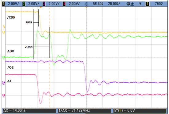
I measured GPMC XIP Timing on TMDXEVM3358.
The /CS0 wave is different from TRM definition.
Question:
- I think tCEon = 0.
How do you think about this? (Is this typo of TRM?)
- How do you think about 6nsec delay existing on the /CS0?
my setting is :
SYSBOOT[15:0] = 0100000100011010b
TRM description: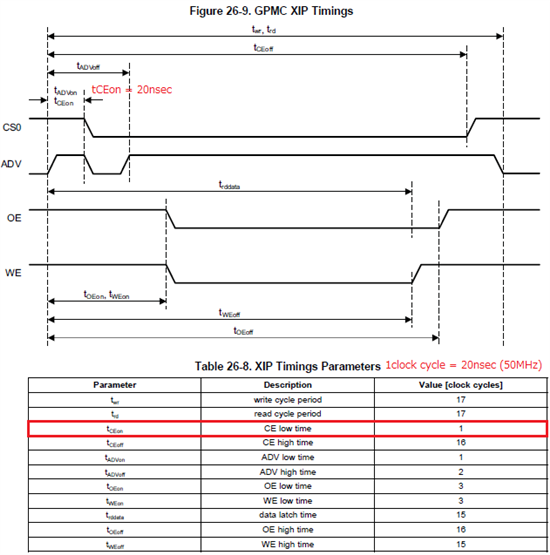
Actual wave: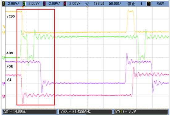
Best regards, RY
Hi folks,
I am working on a temperature measurement project. The current design is to connect a RTD(PT100) and a reference resistor(0.01%) in series, drive them with a constant current source and then measure the voltage across both RTD and reference resistor by SD24 ADC simultaneously, calculate the resistance of RTD and deduct temperature from the resistance of RTD. The circuit works reasonably well in terms of repeatability and precision. The problem is accuracy. I am trying to develop a calibration strategy which will rely on error analysis and calculation.
The errors come from the following sources: 1) nonlinearity of SD24 ADC; 2) offset error of SD24 ADC; 3) the gain error of PGA; 4) inaccuracy of reference resistor.
The datasheet of MSP430F6720 that is used in the project states the error of 1) is about 0.01%, when RTD is close to reference resistor, this part of error is really neglectable. error of 2) can be as high as 73mV, but this can be calibrated in software so not a big deal.
What really beats me down is the error of PGA gain, it is as high as 2%. Even when gain = 1, it is still 1%. That means roughly 4% error in the measured resistance of RTD if my calculation is right. If the reference is 80ohm, the error could be up to 3.2ohm, an error of rough 8 degree C in temperature. Of course in reality it is not this bad. The initial accuracy of my first 10 boards is usually within +/-0.3C.
My question is, is the error of pga gain consistent over time for each particular MCU? If that is true, since this is largely offset error, I can calibrate the measurement circuit against a reference temperature.
Please advise and thanks in advance.
Hi,
I am just starting with msp430 microcontrollers, so I bougth the msp-exp430f5529lp. I have installed mspdebbug-0.22, and energia, but I prefer command working, I can see by the kernel log that the lp is recognized and typing lsusb
I can see this:
Bus 002 Device 014: ID 0451:2046 Texas Instruments, Inc. TUSB2046 Hub
Bus 002 Device 015: ID 2047:0013 Texas Instruments
now typing mspdebug --usb-list:
Devices on bus 002:
002:015 2047:0013 [serial: 384F0C471A001900]
002:014 0451:2046
002:001 1d6b:0001 [serial: 0000:00:1d.0]
So the launchpad is being recognized, but when I try to use: mspdebug tilib
results:
MSP430_GetNumberOfUsbIfs
MSP430_GetNameOfUsbIf
No unused FET found.
And typing: mspdebug rf2500
results:
rf2500: failed to open RF2500 device
I have tried using the -U parameter, in this case it would be: mspdebug -U 002:014 rf2500, but it stills don't work, I know you didn't do the mspdebug or energia utilities (or I think so), but maybe this problem is usual and you can give me a possible solution.
Or if you have another open-source utility usable by command prompt I don't have any problem testing it. By energia when I click on upload appears the same message:
MSP430_GetNumberOfUsbIfs
MSP430_GetNameOfUsbIf
No unused FET found.
Daniel Garcia