Quantcast
Channel: Forums - Recent Threads
Viewing all 262198 articles
Browse latest View live

Still unclear which parameters have to be scaled with ipscale=1

$
0
0

Part Number: BQ78350-R2-DEVICE-FW

Hi,

after spending many hours of reading all documentations, incl. datasheet, app-notes, presentation on the "high discharge rate scaling" i am still unsure which parameters have to be scaled.

I want to use IPSCALE=1 to support current measurements up to 320A (instead of 32.768A.

Question: Do all parameter related to "current in mA" need to be reescaled by factor 0.1 (divied by 10)? I found more than 54 parameters?

Please help...?

* Field Order: Class nameSubclass nameParameter nameParameter ValueDisplay Units
CalibrationCurrent DeadbandDeadband10mA
CalibrationCurrent DeadbandCoulomb Counter Deadband38264nV
ProtectionsOCCThreshold11000mA
ProtectionsOCCRecovery Threshold10000mA
ProtectionsOCDThreshold-30000mA
ProtectionsOCDRecovery Threshold-28000mA
ProtectionsPTOCharge Threshold2000mA
ProtectionsPTOSuspend Threshold1800mA
ProtectionsPTOReset2mAh
ProtectionsCTOCharge Threshold2500mA
ProtectionsCTOSuspend Threshold2000mA
ProtectionsCTOReset2mAh
ProtectionsOCThreshold1000mAh
ProtectionsOCRecovery10mAh
Permanent FailSOCCThreshold28000mA
Permanent FailSOCDThreshold-28000mA
Permanent FailVIMRCheck Current10mA
Permanent FailCFETOFF Threshold5mA
Permanent FailDFETOFF Threshold-5mA
Advanced Charge AlgorithmLow Temp ChargingCurrent Low132mA
Advanced Charge AlgorithmLow Temp ChargingCurrent Med352mA
Advanced Charge AlgorithmLow Temp ChargingCurrent High264mA
Advanced Charge AlgorithmStandard Temp ChargingCurrent Low1980mA
Advanced Charge AlgorithmStandard Temp ChargingCurrent Med4004mA
Advanced Charge AlgorithmStandard Temp ChargingCurrent High2992mA
Advanced Charge AlgorithmHigh Temp ChargingCurrent Low1012mA
Advanced Charge AlgorithmHigh Temp ChargingCurrent Med1980mA
Advanced Charge AlgorithmHigh Temp ChargingCurrent High1496mA
Advanced Charge AlgorithmRec Temp ChargingCurrent Low2508mA
Advanced Charge AlgorithmRec Temp ChargingCurrent Med4488mA
Advanced Charge AlgorithmRec Temp ChargingCurrent High3520mA
Advanced Charge AlgorithmPre-ChargingCurrent100mA
Advanced Charge AlgorithmMaintenance ChargingCurrent44mA
Advanced Charge AlgorithmTermination ConfigCharge Term Taper Current450mA
Fuel GaugingCurrent ThresholdsDsg Current Threshold20mA
Fuel GaugingCurrent ThresholdsChg Current Threshold20mA
Fuel GaugingCurrent ThresholdsQuit Current10mA
Fuel GaugingDesignDesign Capacity mAh9000mAh
Fuel GaugingDesignDesign Capacity cWh19440cWh
Fuel GaugingStateLearned Full Charge Capacity9000mAh
Fuel GaugingCEDV cfgFCC Learn Up1024mAh
Fuel GaugingCEDV cfgFCC Learn Down1024mAh
Fuel GaugingCEDV cfgOverLoad Current30000mA
Fuel GaugingCEDV cfgNear Full200mAh
Fuel GaugingCEDV cfgReserve Capacity0mAh
PowerSleepSleep Current20mA
PF StatusDevice Current DataCurrent0mA
SBS ConfigurationDataRemaining AH Cap. Alarm300mAh
SBS ConfigurationDataRemaining WH Cap. Alarm432cWh
LifetimesCurrentMax Charge Current0mA
LifetimesCurrentMax Discharge Current0mA
LifetimesCurrentMax Avg Dsg Current0mA
LifetimesCurrentMax Avg Dsg Power0cW

TPS40210: TPS40210

$
0
0

Part Number: TPS40210

I use 5V input and 12V output; when the output load suddenly increases, my input voltage will be pulled down to 4V, please ask how to solve

CCS/LAUNCHXL-F28379D: CAN BUS Communication: ACK Missing

$
0
0

Part Number: LAUNCHXL-F28379D

Tool/software: Code Composer Studio

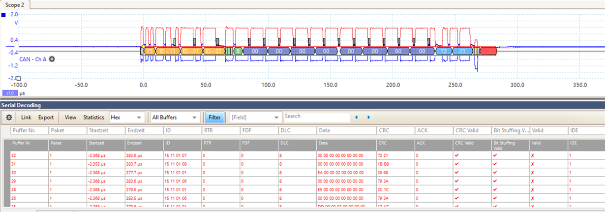
I am using the CAN Interface w/Tranceiver (GPIO12, GPIO17) to communicate with a control board via CAN BUS Communication (500kbit/s and extended data frame).

I am very new in this type of communication and till now I already receive the information from the control board via the CAN Bus.
However,  analyzing the CAN BUS with the Piscoscope6, the ACK and the VALID Fields are always 0 (NULL).

How is the ACK manipulated in the F28379d?

I am asking this because when I am sending data frames the ACK is also 0 and I do not know if the ACK changes the behavior of the control board:

Thank you in advance for helping me!

TMS320F28335: Code port on TMS320F28335

$
0
0

Part Number: TMS320F28335

Hello sir,

I have to port my project on tms320f28335 which is now on tms320f2806.Need some guidance.

The project uses peripherals  like PWM,SCI,I2C,External interrupt and ADC.

I don't know how to proceed.

Both of them work on different frequency

F28335 has 150Mhz

F2806 has 100Mhz

Adc reference is also different.

Need some guidance in this.

Please help.

Non-inverting type 2 and 3 compensators

$
0
0

Hi

I am familiar with inverting Type 2 and 3 compensators, I have stabilized many DC/DC converters (buck boost ...) with these types. I could derive and manipulate (Poles and Zeros) the transfer function of these compensators. These last days, I am faced with "Non-inverting type 2 and 3 compensators". The topology i found in some sites did nont convince me.

Please can anyone guide me to PDF file that deals in depth with this kind of compensators ?? 

LMK04821: SDCLKoutY_FMT can not be set to HSDS 10mA, LVPECL 1600/2000 or LCPECL

$
0
0

Part Number: LMK04821

SDCLKoutY_FMT can not be set to HSDS 10mA, LVPECL 1600/2000 or LCPECL. Any value greater than 0x30 written to 0x116 (SDCLKout5_FMT) stops the output. Thank you in advance for any suggestions.

DS90UH948-Q1: DS90UH949-Q1 touch panel

$
0
0

Part Number: DS90UH948-Q1

Dear TI Exprts

Our customer is using  serializer  DS90UH949-Q1  and  deserializer is DS90UH948-Q1 and a touch panel over I2C of the deserializer(DS90UH948-Q1).

Now they met with a problem need your help: Touch Panel  cannot be used normally

At most of the time, touch panel can work normally, but sometimes it cannot be used,rebooting the system will return to normal.

When the touch panel cannot be used, the I2C CLK of  949  is pulled to 0V; the I2C CLK and data  of 948 are normal(High)

Can you give me any advices? Thank you very much~


TPA3116D2: Can AM0, AM1, AM2 be left floating?

$
0
0

Part Number: TPA3116D2

Can AM0, AM1, AM2 inputs be left floating instead of grounded (this seems to work on my prototype board)? I would like to optionally tie them to PVDD thru a pull-up resistor for testing, but if no pull up is installed have them default to a "low" logic level. The data sheet is a bit vague on this.


INA148: INA148+MUX507 protection

$
0
0

Part Number: INA148

Dear Marek, please answer

I need to receive signals from two wire line, please, see attach.

I think it would be right to put INA148 at the input of the line (at the input of the multiplexer MUX507). But we have a lot of lines and putting INA148 at the input of each line is expensive.

How do you think, does it make sense to install resistors R3 and R4 to protect MUX507 and what value should they be taken?

TIA

Sincerely,

Vladimir Naumenkov

www.agat.by

(Please visit the site to view this file)

CCS/TMS570LS1224: Problems with scinotification() and global variables using HalCogen and CCS

$
0
0

Part Number: TMS570LS1224

Tool/software: Code Composer Studio

Hi,

I've been having some trouble with an issue I can't really understand. I'm using Halcogen and CSS to create a program in which the TMS570LS1224 receives some messages via RX pin using interrupts. That seems to work well, but then I wanted to use some variable to keep track of how many messages the TMS570LS1224 receives, so I created a global value (declared outside any function) which I called j  for this purpose. The problem is everytime I enter scinotification(), that variable somehow changes its value for seemingly no reason so it doesn't work as expected (it should be incremented by one everytime a new message is received). Can someone help me with this? 

This is my code:

#include "sci.h"
#include "stdlib.h"
#include "sys_common.h"

static unsigned char npulses;
uint8_t j = 0;

int main(void)
{

_enable_IRQ();

sciInit();

sciReceive(sciREG,9,(unsigned char *)&npulses);

while(1);

}

void sciNotification(sciBASE_t *sci, unsigned flags)
{
 j++;
sciSend(scilinREG, 9, (unsigned char *)&npulses); 

sciReceive(sciREG,9,(unsigned char *)&npulses);

return;

}

void esmGroup1Notification(int bit)
{
return;
}

void esmGroup2Notification(int bit)
{
return;

}

EVM430-FR6047: USS (gui) connect and other issues with example water flow meter app

$
0
0

Part Number: EVM430-FR6047

Hello.

Recently received EVM MSP430-FR6047. USS initially loaded fine and would indicate that it connected successfully with preloaded example app loaded on evm board. Evm board when powered on would immediately begin generating pulses to transducers (alternating between the two) -- could see this on scope. LED1 & LED2 were off but LED3 was red. GUI logged "no signal up and down" error, but was able to "capture" (on ADC capture tab) what looked similar to the example wave form from the docs.

Read a number of posts about various issues others were experiencing and since other attempts seem to have no affect  (same error message collecting in log), so I tried to flash the latest image "UltrasonicWaterFR604x_02_20_00_08".  Now LED3 is off, D201 still solid green, D202 flashing as before, no longer pulsing transducers on startup, but GUI no longer able to connect. At times says "Connected waiting device" or "No connected HID devices"...  I think the latter may be because the first attempt left the HID device is some "busy" state., since reattempting "Connect"  will either get no response or "Connected -- waiting ..." message.  Tried to flash with other versions, reinstalled gui. Tried to compile and flash example project from USS (gui) installation directory (USS_02_20_00_18). Only getting variations of the above non-connect messages.

USB connectivity has not changed.. Unplugged & plugged back in a few times. Restarted/rebooted computer in case windows getting confused. Same results.

At this point, transducers aren't even part of the equation.. All jumpers are as indicated in "getting started/hw" doc and have remained the same since it first was connecting. Can't get GUI (USS windows app) to connect as it did when first received.

Did notice one other thing. When compiled and flashed sample project from directory where GUI was installed, a warning about "old silicone" was displayed.

Did also try same sample app by downloading from web via "resource center" in case code was updated. No change in behavior -- GUI can't successfully connect.

Any suggestions appreciated.

AMC1300: Parallel operation of the AMC1300 for current measurement.

$
0
0

Part Number: AMC1300

Dear sir,

we are trying to measure the current (4 ch) & voltage (4 ch) using AMC1300. All channels are connected in parallel. 

All the 8 qty of AMC1300 high side are supplied by 5V source PS1. All the 8 qty of AMC1300 low side are supplied by 5V source PS2. 

When we measure same current in all the four channel, everything works fine. we can able measure the same value in all the four channels. 

If we connect current measurement board to measure the three phase inverter output current, Resistance R51 and R55(as shown in the below picture) are burned.  All the filter resistance used in the current measurement circuits are burned. The voltage measurement circuit was working fine. 

please find the below attached project file.

(Please visit the site to view this file)

Kindly guide us to proceed further in current measurement using AMC1300.

Thanking you.

Thanks & regards,

Rajasekaran.

CCS/CC1310: cc1310 module e70 unlocked debug

$
0
0

Part Number: CC1310

Tool/software: Code Composer Studio

Sorry in your question. You indicated that you need to change

the configuration and how to do it specifically?

I just have the same situation with e70). thank

LM723: Vz in the metal can package

$
0
0

Part Number: LM723

Hi,

It says in the datasheet "For metal can applications where VZ is required, an external 6.2V zener diode should be connected in series with VOUT.", does this mean I should just connect the Vz input to Vout through a diode? Attached is the circuit diagram from page 13 of the datasheet.

Thanks.

AM5728: I/O isolation and DDR3 self-refresh

$
0
0

Part Number: AM5728

I'm trying to determine if it's possible to temporarily reenter I/O isolation mode without loss of the contents of DDR3 memory, to be able to reconfigure padconf/iodelay at a later point in u-boot. I had hoped to use some helper code in internal SRAM that puts the DDR3 into self-refresh, enters I/O isolation, performs the reconfiguration, leaves I/O isolation, takes DDR3 out of self-refresh, and returns execution to code in DDR3.

The problem is that to keep DDR3 in self-refresh, CKE needs to be driven low through all this, but my impression is that the DDR3 CKE signals are not exempt from I/O isolation, which means they'd get pulled to VTT resulting in undefined behaviour.

Can you confirm that I/O isolation mode will indeed cause all DDR3 signals to go high-Z, including CKE?

If so, then it would probably be a good idea to recommend am57xx users to use a gpio-controlled switchable VTT supply that's disabled by default to prevent the DDR3 cmd/addr signals from being pulled to VDD_DDR/2 during I/O isolation, which could cause undefined behaviour in the ram and/or excessive current in the ram's input buffers. (It would be desirable to reset the ram if this were to happen, but it is very unclear when exactly EMIF asserts the ddr3 reset signal and whether software can request it to do so.)


OPA858: Regarding PD and supply product

$
0
0

Part Number: OPA858

To whom it may concern,

I have a single-ended input signal range of 0V~0.5V and a single-ended output range of 0V to 3V, and I need a bandwidth of more than 800MHz for a capacitive load <2pF.

Based on simulation and reading, I find OPA858 to be very suitable. 

Signal 1: analog low swing

Signal 2: digital high swing 

Now I have two questions:

1. I find that I need an unbalanced split supply of -1V and 4V for non-inverting amplification. Thus, is there any recommended TI LDO that can generate -1V and 4V together conveniently?

2. If the amplifier is in power down mode, with Vin+ still connected to a voltage within the input range, and supplies still connected to -1V and 4V, can I short the output to 0V?

Please advice.

Thank you.

Weiyu 

BQ78350: CHG and DSG disabled without any protection register enabled.

$
0
0

Part Number: BQ78350

Hi.

I have the combination  BQ78350 with BQ7693000DBT.

In some occations DSG and CHG are disabled, when I read the registers,  no protection register is enabled  and the only way to activate again the DSG and CHG are restarting the BQ78350.

So, what is the possible cause that generate that problem?

And, how could I avoid that problem?

Thanks for the answers

LMX2492: FMCW and integer boundaries

$
0
0

Part Number: LMX2492

Hi,

I want to perform a linear FMCW sweep from 13.4 to 14.0 GHz using a 100 MHz reference (I can change the XO frequency if you have another recommendation).

When performing such a wide sweep across 5 integer boundaries can I expect LMX2492 to maintain a "clean sweep" without any RF phase or amplitude discontinuities near the boundaries? This is critical for proper FMCW operation.

Related to this, I also read somewhere on this forum that the fractional counter can only "roll over 8 times". I guess that means one can only sweep across 8 integer boundaries? Are there other such limitations/considerations I should know about?

Thanks!

Christer

CCS/UCD3138PFCEVM-026: PWR026_PFC

$
0
0

Part Number: UCD3138PFCEVM-026

Tool/software: Code Composer Studio

What does i_target_offset meaning ?

What is i_target_offset used to do?

CCS/UCD3138PFCEVM-026: PWR026_PFC

$
0
0

Part Number: UCD3138PFCEVM-026

Tool/software: Code Composer Studio

codes in .asm and .obj profile are constants?

If .c and .h have been dbugged , .asm and .obj need to be debugged?

Viewing all 262198 articles
Browse latest View live


<script src="https://jsc.adskeeper.com/r/s/rssing.com.1596347.js" async> </script>