Quantcast
Channel: Forums - Recent Threads
Viewing all 262198 articles
Browse latest View live

DP83TC811S-Q1: DP83TC811S-Q1 EMC issue

$
0
0

Part Number: DP83TC811S-Q1

Dear TI team:

We encountered some problems when testing EMC,please help to analyze:

We use dp83tc811s-q1 Ethernet chip (Master device) to assist test another dp83tc811s-q1 Ethernet chip (Slave device). But when Master device is working, the RE and CE test's environmental noise the test results will be greatly affected at 30M~200M, as below:

-- RE Master device is working

-- RE Master device is power off

-- CE Master device is working

-- CE Master devices is power off

We also did the verification test as below:

We use the same dp83tc811s-q1 Ethernet chip device, and download Master and Slave software separately. Then we do the RE and CE test, the test result is close to the above.

Please help us to check whether it can be optimized by hardware and software design?

Thanks!

Regard!

ZeKun.Wang


AWR1843BOOST: Additional caps on LC filter in xWR1843boost Rev.C

$
0
0

Part Number: AWR1843BOOST

Hi expert,

Customer ask in xWR1843boost Rev.C we added some caps on LC filter (compare to Rev.B)

Added 22uF caps to 1V, 1.24V, and 1.8V LC filters
Added 10uF caps to 3.3V and 1.24V LC filter
Added additional 10uF caps to 1V LC filter

In AWR1843 hardware check list it suggests a 0.22uF and a 10uF decap on RF1 and RF2 power input.

Question is

Which one we should follow? Checklist or Rev.C schematics?

Do you have ripple measurement comparison result  between Rev.B and Rev.C? 

Regards,

Allen

CCS: How CCS can support remote debug

$
0
0

Tool/software: Code Composer Studio

Hi

      i want to know that if CCS can support remote debug feature, that is A runs CCS in local computer, and the board in remote place which can connect with another remote computer,  and there is no source code runs in remote computer for the consideration of confidentiality, then engineer can debug the code with local computer with CCS.

    Can you help check if CCS can support this function? Thanks.      

AM3352: am3352 i2c issue

$
0
0

Part Number: AM3352

When the system starts up, it will have the following information:

(Please visit the site to view this file)

This phenomenon is probabilistic. I keep restarting the board, more than 500 times appeared.

Because PMIC is on this I2C bus, the system can not start.

The SDK version we used is: 05.03.00.07

Do you have any suggestions for reference?

CCS/LAUNCHXL-CC26X2R1: write/read the Internal Flash of CC2652

$
0
0

Part Number: LAUNCHXL-CC26X2R1

Tool/software: Code Composer Studio

Hi,

we want store 512Bytes @address 0x10000 ,and 712Bytes@address 0x10400 to the internal Flash of CC2652, does ti can provide us the Flash read/write  example ? 

Thanks,

LN

CC3220MODA: AT+GET=[General],[version]

$
0
0

Part Number: CC3220MODA

Dear Sir,

I want to use AT command = to check RF performance for the chip(CC3220MODA).

I type  AT+GET = [General],[Version]  but it show fail "ERROR: parse parameters,-4".

Could you teach me how to run the at command.

PS: AT+Start  and AT+Stop=1  : 2 command is OK.

My present version:  "at_commands.bin"  and  "sp_3.12.0.1_2.0.0.0_2.2.0.6.bin".

TPS61030: Power save mode and the set threshold voltage

$
0
0

Part Number: TPS61030

Hi,

In the datasheet of TPS61030, it says that "In power save mode the converter only operates when the output voltage trips below a set threshold voltage. It ramps up the output voltage with one or several pulses and goes again into power save mode once the output voltage exceeds the set threshold voltage."

My questions:1. What is the threshold? I have not seen the detail explanation of how to set the threshold.

2. How is this function realized? In the block diagram, I can't find anything about the threshold or the comparator to control the switch once the output voltage exceeds or trips below the set threshold voltage.

Thanks&Best Regards,

Wenxiu

TDA2SG: SoC Type Selection Consultation

$
0
0

Part Number: TDA2SG

Hi,

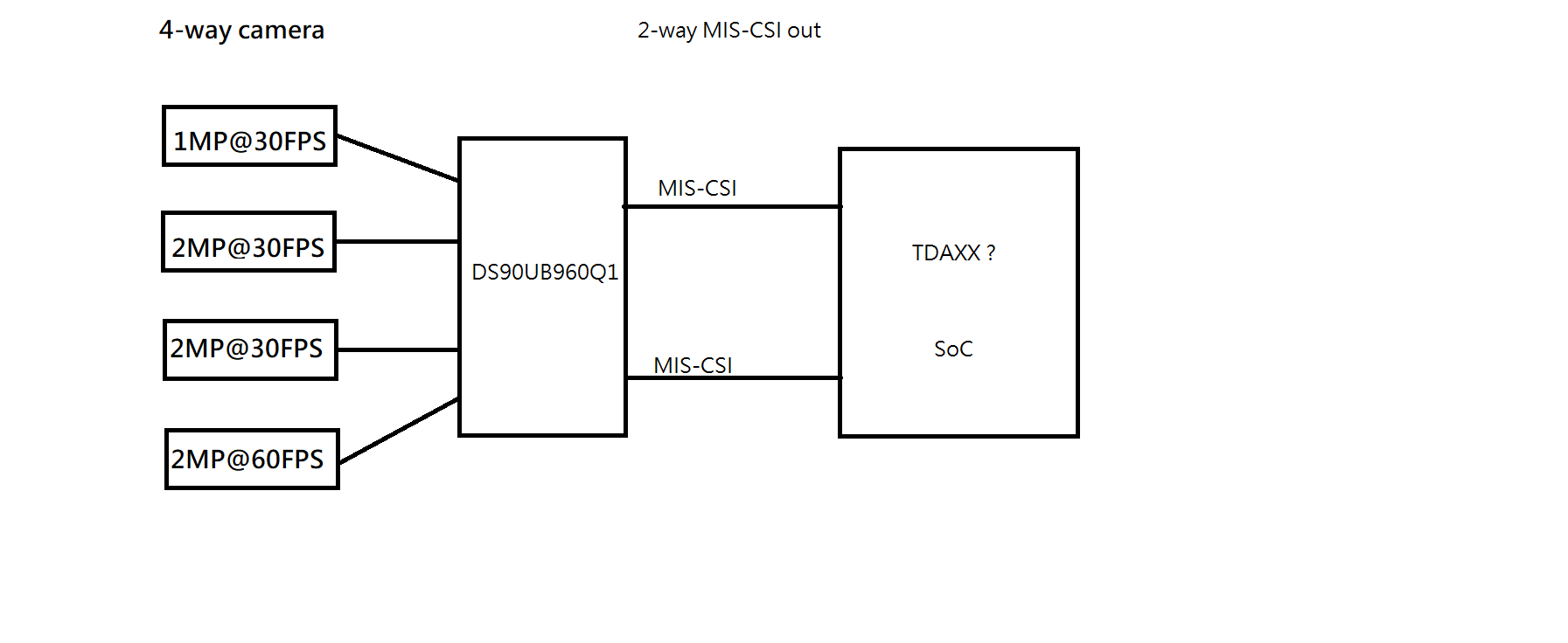
     I need use SoC on my auto product, but I am not sure which one is suitable.

    Need TI member suggestion.

    my application function block as below;

Could you suggest suitable SoC IC for my application?

thanks.


TM4C1294KCPDT: How to check the External oscillator and switch the clock source when main oscillator fail

$
0
0

Part Number: TM4C1294KCPDT

Hello everyone:

The function I want to design is when MCU lose the main external oscillator, it could switch the Clock source to Internal Clock source 、keep the code running i and get the external main oscillator fault flag

The following are the ways I tried:

1、Detect the register MOSCCTL (I don't set any bit of it), when the code is running, the bit OSCRNG(High Frequency Range (equal to or greater than 10 MHz).) was 1 when the rest were 0. After I cut off the external oscillator, the code jump into Hard_fault handler automatically and register MOSCCTL didn't has any changes.

2、When I used j-link simulator to simulate the MCU, I cut off the external oscillator. In most case, the code will jump to Hard_Fault Handler, but sometimes it will jump to bus_fault or memery_fault. What's more, when code jump into hard_fault handler, it need me to click single step run the code, it can't run in full speed and sometimes it even didn't run and register PC  didn't count when I click single step. So it 's difficult to me to judge whether the MCU was still working.

3、I have some idea that when the external oscillator fail, it could reboot the MCU and when it decides which clock source to use according to bit MOSCPUPIM in register IMC and set a flag which means MCU lost external oscillator last time when it initialize the MCU. There are 2 defects, one is when it repower MCU, the bit  MOSCPUPIM  will be clear; two is when clock fault happen,it don't have time to do the emergency operation such as control GPIO to cut off some breaker.

It is very kind of you if you have any ideas could share to me.

Thank you all

TDA4: Understanding of the performance benchmarks of the TIDL 0.9 release on the J7ES EVM

$
0
0

I have a customer interested in a bit more of the details of a presentation provided which includes Proc time (ms) and FPS for a variety of Networks, but specifically MobileNetV2 and ssd mobilenet v2 SSD. They would like the load specifically at the MMA, C7x, A72 and memory bandwidth. 

TMS570LS1227: How to enable Pwm_Het1EdgeNotifyInterrupt

$
0
0

Part Number: TMS570LS1227

Hi team,

In my project the Pwm_Het1EdgeNotifyInterrupt is needed

.

Follow the user manual I have enabled the PwmNotificationSupported feature and config the PWM as CAT 2 interrupt

And config the notification function as below

In the user manual I can not find which interrupt address shall be assign to this interrupt. Can you help to tell me how to config the vector table for this interrupt in OS?

I have configured as ePWM1(396), but the interrupt is not happened.

Does the port pin in PORT module shall also be updated?

TPS65094: TPS650942A0 Reset Issue

$
0
0

Part Number: TPS65094

Hello

             Customer use TPS650942A0. They found that TPS650942A0 (use for apollo lake) resets( RSMRSTB pin 16) at temperatures between 0 and -10 ° C. PV1P24A (1.24V) looks OVP about 1.96V so cause PMIC reset output (PMIC_RSMRST) to High to Low to reset CPU. Why cause power fault condition at low 0 and -10 ° C ?

              If over +5° C temperature operating, there is no power fault to cause reset condition. We also find the same issue on another post. 

https://e2e.ti.com/support/power-management/f/196/t/763009?tisearch=e2e-sitesearch 

BR

Patrick

LP5569: Enable Issue

$
0
0

Part Number: LP5569

Dear Team,

When I was using the LP5569,
When I turn the LEDs on,
Then I pulled the pin of EN/PWM down,
But the LEDs are still on, and you can continue to follow the instructions.

If the EN/PWM pin is first pulled low after power-on,
After the initial control IC, it will not be initialized at this time, and the command cannot be executed.


The LP5562 is used without this problem.
First turn the LED on, then EN/VCC pin pulls Low,
The LED will go out,

If the pin of EN/VCC is pulled first after power-on,
After the initial control IC, it will not be initialized at this time, and the command cannot be executed.


I don't know if my initial control IC program/step is wrong?
Init of LP5562:
I2cset -y 0 0x30 0x0 0x40
I2cset -y 0 0x30 0x70 0x0

Init of LP5569:
I2cset -y 0 0x40 0x0 0x40

BR

Kevin

BQ76200: BQ76200 damage mosfet

$
0
0

Part Number: BQ76200

     I use BQ76200 to driver high side MOSFET, it will damage the MOSFET when short test. The short current is 540A.How to solution this issue?

The MOSFET Vgs voltage wave as attachment when short.

 (Please visit the site to view this file)

ISOW7841EVM: CMC orientation

$
0
0

Part Number: ISOW7841EVM

Hi,

I am planning to use the CMCs as a fallback option in case of EMI issue in my design (which has four ISOW7841, one ISOW7840 and few other DC/DC power supplies (isolated and non-isolated).

Looking at this thread and suggested CMC placement (layout example), and after checking the footprint of the suggested CMCs, I am a bit confused with the CMC orientation/connection - I believe the CMC should be rotated 90 degs (clock wise or anti-clock wise, doesn't matter because there is no polarity).

Could you please clarify?

Thanks,


CC2530: short address update

$
0
0

Part Number: CC2530

hello,

does the short address of an end device remain the same after leaving and rejoining the same previous network?

thanks

UCD9090A: GPO_CONFIG_X description on generated file from device export in Configuration Tool of Fusion Digital Power Designer

$
0
0

Part Number: UCD9090A

Hello,


My customer wants to generate a report file that describes their own UCD9090A configuration.

I suggested to use device export function in configuration tool of fusion digital power designer tool.

They are trying to use “TextFile” format from device export window.

Then they found an issue in “GPO_CONFIG_X” - “Decoded Numeric” column. The delay is not described on it.


For example, the below is an example configuration for GPO_CONFIG_1 in configuration tool.


And the below is “GPO_CONFIG_1” - “Decoded Numeric” column in the generated file from device export.


Pin 15 FPWM6_GPIO10 ActiveHigh ActivelyDrivenOutput; RAIL1' [VOUT_UV_FAULT]


There is no delay information in it. Is there any way to add delay information in the report file?


Regards,

Oba

TMS570LC4357: TMS570LC4357

$
0
0

Part Number: TMS570LC4357

 I want to get  cap/cover for the -hercules  launchpad trimmer potentiometer-  to can use it easily ?

TMDSCNCD280049C: I find that U4:A 8pin & 6pin is not connet to EMU_3V3 in PCB of MCU009B_Altium.zip , that is different from SchDoc .

$
0
0

Part Number: TMDSCNCD280049C

I find that U4:A 8pin & 6pin is not connet to EMU_3V3 in PCB of MCU009B_Altium.zip , that is different from SchDoc .

Is U4:A 8pin & 6pin  wrong in PCB ?

PCB picture :

SchDoc :

OMAPL138B-EP: Omapl138 DDR2 connection

$
0
0

Part Number: OMAPL138B-EP

Hi,

The customer connected omapl138 with MT46H64M16LFBF-5 up to 1Gb by multiple DDRs, now he wants to upgrade to 2Gb LPDDR, how to connect in hardware?

Viewing all 262198 articles
Browse latest View live