Quantcast
Channel: Forums - Recent Threads
Viewing all 262198 articles
Browse latest View live

CCS/AWR1642BOOST: Errors during install

$
0
0

Part Number:AWR1642BOOST

Tool/software: Code Composer Studio

Hello team,

My customer is having trouble installing software for the AWR1642BOOST - description below. Any insight into next steps?

There are a couple of errors with the gcruntime-7.0.0-windows-installer.exe. First, in the Setup Installation Directory dialog boxes, it shows the same dialog box, yet it needs two different paths for installing the S/W. In the log file (copied below with first error message), you will see Errors that took place during the installation when the drivers are attempted to be installed. If you have corrected this problem, and have a location where I can download a corrected version of this installation, please let me know.

ERROR MESSAGES SEEN BY THE CUSTOMER:

[07:36:41] About to run C:\Program Files (x86)\Texas Instruments\guicomposer\runtime\gcruntime.v7/win32/TICloudAgentHostApp/util/install-certs.bat
Executing C:\Program Files (x86)\Texas Instruments\guicomposer\runtime\gcruntime.v7/win32/TICloudAgentHostApp/util/install-certs.bat
Script exit code: 1

Script output:

C:\Program Files (x86)\Texas Instruments\guicomposer\runtime\gcruntime.v7\win32\TICloudAgentHostApp\util>certutil -addstore "TrustedPublisher" C:\Program Files (x86)\TEXASI~1\GUICOM~1\runtime\GCRUNT~1.V7\win32\TICLOU~2\util\\ti1.p7b
Expected no more than 3 args, received 4
CertUtil: Too many arguments

Usage:
CertUtil [Options] -addstore CertificateStoreName InFile
Add certificate to store
CertificateStoreName -- Certificate store name. See -store.
InFile -- Certificate or CRL file to add to store.
Modifiers:
Certs
CRLs
CTLs
Root
NoRoot

Options:
-f -- Force overwrite
-Enterprise -- (-ent) Use local machine Enterprise registry certificate store
-user -- Use HKEY_CURRENT_USER keys or certificate store
-GroupPolicy -- (-gp) Use Group Policy certificate store
-Unicode -- Write redirected output in Unicode
-gmt -- Display times as GMT
-seconds -- Display times with seconds and milliseconds
-v -- Verbose operation
-privatekey -- Display password and private key data
-pin PIN -- Smart Card PIN
-dc DCName -- Target a specific Domain Controller
-sid WELL_KNOWN_SID_TYPE -- Numeric SID
22 -- Local System
23 -- Local Service
24 -- Network Service

CertUtil -? -- Display a verb list (command list)
CertUtil -addstore -? -- Display help text for the "addstore" verb
CertUtil -v -? -- Display all help text for all verbs


C:\Program Files (x86)\Texas Instruments\guicomposer\runtime\gcruntime.v7\win32\TICloudAgentHostApp\util>certutil -addstore "TrustedPublisher" C:\Program Files (x86)\TEXASI~1\GUICOM~1\runtime\GCRUNT~1.V7\win32\TICLOU~2\util\\ti2.p7b
Expected no more than 3 args, received 4
CertUtil: Too many arguments

Usage:
CertUtil [Options] -addstore CertificateStoreName InFile
Add certificate to store
CertificateStoreName -- Certificate store name. See -store.
InFile -- Certificate or CRL file to add to store.
Modifiers:
Certs
CRLs
CTLs
Root
NoRoot

Options:
-f -- Force overwrite
-Enterprise -- (-ent) Use local machine Enterprise registry certificate store
-user -- Use HKEY_CURRENT_USER keys or certificate store
-GroupPolicy -- (-gp) Use Group Policy certificate store
-Unicode -- Write redirected output in Unicode
-gmt -- Display times as GMT
-seconds -- Display times with seconds and milliseconds
-v -- Verbose operation
-privatekey -- Display password and private key data
-pin PIN -- Smart Card PIN
-dc DCName -- Target a specific Domain Controller
-sid WELL_KNOWN_SID_TYPE -- Numeric SID
22 -- Local System
23 -- Local Service
24 -- Network Service

CertUtil -? -- Display a verb list (command list)
CertUtil -addstore -? -- Display help text for the "addstore" verb
CertUtil -v -? -- Display all help text for all verbs


C:\Program Files (x86)\Texas Instruments\guicomposer\runtime\gcruntime.v7\win32\TICloudAgentHostApp\util>certutil -addstore "TrustedPublisher" C:\Program Files (x86)\TEXASI~1\GUICOM~1\runtime\GCRUNT~1.V7\win32\TICLOU~2\util\\ti3.p7b
Expected no more than 3 args, received 4
CertUtil: Too many arguments

Usage:
CertUtil [Options] -addstore CertificateStoreName InFile
Add certificate to store
CertificateStoreName -- Certificate store name. See -store.
InFile -- Certificate or CRL file to add to store.
Modifiers:
Certs
CRLs
CTLs
Root
NoRoot

Options:
-f -- Force overwrite
-Enterprise -- (-ent) Use local machine Enterprise registry certificate store
-user -- Use HKEY_CURRENT_USER keys or certificate store
-GroupPolicy -- (-gp) Use Group Policy certificate store
-Unicode -- Write redirected output in Unicode
-gmt -- Display times as GMT
-seconds -- Display times with seconds and milliseconds
-v -- Verbose operation
-privatekey -- Display password and private key data
-pin PIN -- Smart Card PIN
-dc DCName -- Target a specific Domain Controller
-sid WELL_KNOWN_SID_TYPE -- Numeric SID
22 -- Local System
23 -- Local Service
24 -- Network Service

CertUtil -? -- Display a verb list (command list)
CertUtil -addstore -? -- Display help text for the "addstore" verb
CertUtil -v -? -- Display all help text for all verbs


C:\Program Files (x86)\Texas Instruments\guicomposer\runtime\gcruntime.v7\win32\TICloudAgentHostApp\util>certutil -addstore "TrustedPublisher" C:\Program Files (x86)\TEXASI~1\GUICOM~1\runtime\GCRUNT~1.V7\win32\TICLOU~2\util\\ti4.p7b
Expected no more than 3 args, received 4
CertUtil: Too many arguments

Usage:
CertUtil [Options] -addstore CertificateStoreName InFile
Add certificate to store
CertificateStoreName -- Certificate store name. See -store.
InFile -- Certificate or CRL file to add to store.
Modifiers:
Certs
CRLs
CTLs
Root
NoRoot

Options:
-f -- Force overwrite
-Enterprise -- (-ent) Use local machine Enterprise registry certificate store
-user -- Use HKEY_CURRENT_USER keys or certificate store
-GroupPolicy -- (-gp) Use Group Policy certificate store
-Unicode -- Write redirected output in Unicode
-gmt -- Display times as GMT
-seconds -- Display times with seconds and milliseconds
-v -- Verbose operation
-privatekey -- Display password and private key data
-pin PIN -- Smart Card PIN
-dc DCName -- Target a specific Domain Controller
-sid WELL_KNOWN_SID_TYPE -- Numeric SID
22 -- Local System
23 -- Local Service
24 -- Network Service

CertUtil -? -- Display a verb list (command list)
CertUtil -addstore -? -- Display help text for the "addstore" verb
CertUtil -v -? -- Display all help text for all verbs


Script stderr:
Program ended with an error exit code

Error running C:\Program Files (x86)\Texas Instruments\guicomposer\runtime\gcruntime.v7/win32/TICloudAgentHostApp/util/install-certs.bat : Program ended with an error exit code
Executing C:\Program Files (x86)\Texas Instruments\guicomposer\runtime\gcruntime.v7/win32/deskdb/content/TICloudAgent/win/install_drivers.bat
Script exit code: 1

Script output:

Script stderr:
Program ended with an error exit code

Error running C:\Program Files (x86)\Texas Instruments\guicomposer\runtime\gcruntime.v7/win32/deskdb/content/TICloudAgent/win/install_drivers.bat : Program ended with an error exit code
Executing C:\Program Files (x86)\Texas Instruments\guicomposer\runtime\gcruntime.v7/win32/TICloudAgentHostApp/drivers/EZ430UART_64.bat
Script exit code: 256

Script output:

C:\Program Files (x86)\Texas Instruments\guicomposer\runtime\gcruntime.v7\win32\TICloudAgentHostApp\drivers>dpinst_64_eng.exe /path EZ430UART /SW /SA

Script stderr:
Program ended with an error exit code

Error running C:\Program Files (x86)\Texas Instruments\guicomposer\runtime\gcruntime.v7/win32/TICloudAgentHostApp/drivers/EZ430UART_64.bat : Program ended with an error exit code
Executing C:\Program Files (x86)\Texas Instruments\guicomposer\runtime\gcruntime.v7/win32/TICloudAgentHostApp/drivers/xds110_drivers_64.bat
Script exit code: 1280

Script output:

C:\Program Files (x86)\Texas Instruments\guicomposer\runtime\gcruntime.v7\win32\TICloudAgentHostApp\drivers>dpinst_64_eng.exe /path xds110_drivers /SW /SA

Script stderr:
Program ended with an error exit code

Error running C:\Program Files (x86)\Texas Instruments\guicomposer\runtime\gcruntime.v7/win32/TICloudAgentHostApp/drivers/xds110_drivers_64.bat : Program ended with an error exit code
Executing C:\Program Files (x86)\Texas Instruments\guicomposer\runtime\gcruntime.v7/win32/TICloudAgentHostApp/drivers/USB_CDC_64.bat
Script exit code: 256

Script output:

C:\Program Files (x86)\Texas Instruments\guicomposer\runtime\gcruntime.v7\win32\TICloudAgentHostApp\drivers>dpinst_64_eng.exe /SW /SA /path USB_CDC

Script stderr:
Program ended with an error exit code

Error running C:\Program Files (x86)\Texas Instruments\guicomposer\runtime\gcruntime.v7/win32/TICloudAgentHostApp/drivers/USB_CDC_64.bat : Program ended with an error exit code

CC2652R: Trying to Understand the GPIO structures in example code

$
0
0

Part Number:CC2652R

Dear Support:

Currently I am using SDK v2.30, but my question is not specific to an SDK.  Seems to occur across all the CC26xx and CC13xx devices.  In the example projects for these devices there is this structure in the CC26X2R1_LAUNCHXL.C flle:

GPIO_PinConfig gpioPinConfigs[] = {
/* Input pins */
GPIOCC26XX_DIO_13 | GPIO_DO_NOT_CONFIG, /* Button 0 */
GPIOCC26XX_DIO_14 | GPIO_DO_NOT_CONFIG, /* Button 1 */

GPIOCC26XX_DIO_15 | GPIO_DO_NOT_CONFIG, /* CC26X2R1_LAUNCHXL_SPI_MASTER_READY */
GPIOCC26XX_DIO_21 | GPIO_DO_NOT_CONFIG, /* CC26X2R1_LAUNCHXL_SPI_SLAVE_READY */

/* Output pins */
GPIOCC26XX_DIO_07 | GPIO_DO_NOT_CONFIG, /* Green LED */
GPIOCC26XX_DIO_06 | GPIO_DO_NOT_CONFIG, /* Red LED */

/* SPI Flash CSN */
GPIOCC26XX_DIO_20 | GPIO_DO_NOT_CONFIG,

/* SD CS */
GPIOCC26XX_DIO_21 | GPIO_DO_NOT_CONFIG,

/* Sharp Display - GPIO configurations will be done in the Display files */
GPIOCC26XX_DIO_24 | GPIO_DO_NOT_CONFIG, /* SPI chip select */
GPIOCC26XX_DIO_22 | GPIO_DO_NOT_CONFIG, /* LCD power control */
GPIOCC26XX_DIO_23 | GPIO_DO_NOT_CONFIG, /*LCD enable */

};

Notice that there 11 entries in this structure.  Also in this same file, there is this structure:

const PIN_Config BoardGpioInitTable[] = {

CC26X2R1_LAUNCHXL_PIN_RLED | PIN_GPIO_OUTPUT_EN | PIN_GPIO_LOW | PIN_PUSHPULL | PIN_DRVSTR_MAX, /* LED initially off */
CC26X2R1_LAUNCHXL_PIN_GLED | PIN_GPIO_OUTPUT_EN | PIN_GPIO_LOW | PIN_PUSHPULL | PIN_DRVSTR_MAX, /* LED initially off */
CC26X2R1_LAUNCHXL_PIN_BTN1 | PIN_INPUT_EN | PIN_PULLUP | PIN_IRQ_BOTHEDGES | PIN_HYSTERESIS, /* Button is active low */
CC26X2R1_LAUNCHXL_PIN_BTN2 | PIN_INPUT_EN | PIN_PULLUP | PIN_IRQ_BOTHEDGES | PIN_HYSTERESIS, /* Button is active low */
CC26X2R1_LAUNCHXL_SPI_FLASH_CS | PIN_GPIO_OUTPUT_EN | PIN_GPIO_HIGH | PIN_PUSHPULL | PIN_DRVSTR_MIN, /* External flash chip select */
CC26X2R1_LAUNCHXL_UART0_RX | PIN_INPUT_EN | PIN_PULLDOWN, /* UART RX via debugger back channel */
CC26X2R1_LAUNCHXL_UART0_TX | PIN_GPIO_OUTPUT_EN | PIN_GPIO_HIGH | PIN_PUSHPULL, /* UART TX via debugger back channel */
CC26X2R1_LAUNCHXL_SPI0_MOSI | PIN_INPUT_EN | PIN_PULLDOWN, /* SPI master out - slave in */
CC26X2R1_LAUNCHXL_SPI0_MISO | PIN_INPUT_EN | PIN_PULLDOWN, /* SPI master in - slave out */
CC26X2R1_LAUNCHXL_SPI0_CLK | PIN_INPUT_EN | PIN_PULLDOWN, /* SPI clock */

PIN_TERMINATE
};

Notice that there are 10 entries.  So why do you have these 2 structures in this file with different numbers of entries in them?  It looks like you are using the 2nd structure and not the 1st.  And if that is the case, why do you have the 1st structure in this file since you are not using it, or are you?

And this is different from the way the CC322x guys define the GPIO pins - they use the 1st structure only and don't have this 2nd structure.  So why is that?  Why not use the same way of doing things across all devices?  I thought that was one of the objectives of the Simplelink architecture.  Please advise as to why the difference.

Thanks,
Tim

CCS/CC1352R: Bug in simplelink_cc13x2_sdk_2_30_00_45/examples/rtos/CC1352R1_LAUNCHXL/ti154stack/coprocessor

$
0
0

Part Number:CC1352R

Tool/software: Code Composer Studio

Hi,

just downloaded simplelink_cc13x2_sdk_2_30_00_45 from tirex. It is currently impossible to import simplelink_cc13x2_sdk_2_30_00_45/examples/rtos/CC1352R1_LAUNCHXL/ti154stack/coprocessor into CCS (just updated to CCS9).

Fix: remove the .project file located in that directory.

CCS/MSP432P401R: MSP low-power microcontroller forum

$
0
0

Part Number:MSP432P401R

Tool/software: Code Composer Studio

Hi All,

I recently upgraded to CCS9 and after getting my projects setup and compiling, I tried to upgrade CCS9, because there were some updates, including a JLink one.  I have a JLink programmer, but don't usually use it.  The upgrade had some problems, but I went on to try to flash an EXP-MSP432P401R red board.  I got the following error:

Sketch uses 40216 bytes (15%) of program storage space. Maximum is 262144 bytes.
Global variables use 25740 bytes (39%) of dynamic memory, leaving 39796 bytes for local variables. Maximum is 65536 bytes.
DSLite version 8.2.0.1400
Configuring Debugger (may take a few minutes on first launch)...
Initializing Register Database...
Initializing: CS_DAP_0
Executing Startup Scripts: CS_DAP_0
Initializing: CORTEX_M4_0
Executing Startup Scripts: CORTEX_M4_0
Connecting...
fatal: CS_DAP_0: Error connecting to the target: (Error -260 @ 0x0) An attempt to connect to the XDS110 failed. The cause may be one or more of: no XDS110 is connected, invalid firmware update, invalid XDS110 serial number, or faulty USB cable. The firmware and serial number may be updated using the xdsdfu utility found in the .../ccs_base/common/uscif/xds110 directory of your installation. View the ReadMe.txt file there for instructions. (Emulation package 8.0.27.9)
Failed: Operation was aborted
the selected serial port Failed: Operation was aborted
does not exist or your board is not connected

Sketch uses 40216 bytes (15%) of program storage space. Maximum is 262144 bytes.
Global variables use 25740 bytes (39%) of dynamic memory, leaving 39796 bytes for local variables. Maximum is 65536 bytes.
DSLite version 8.2.0.1400
Configuring Debugger (may take a few minutes on first launch)...
	Initializing Register Database...
	Initializing: CS_DAP_0
	Executing Startup Scripts: CS_DAP_0
	Initializing: CORTEX_M4_0
	Executing Startup Scripts: CORTEX_M4_0
Connecting...
fatal: CS_DAP_0: Error connecting to the target: (Error -260 @ 0x0) An attempt to connect to the XDS110 failed. The cause may be one or more of: no XDS110 is connected, invalid firmware update, invalid XDS110 serial number, or faulty USB cable. The firmware and serial number may be updated using the xdsdfu utility found in the .../ccs_base/common/uscif/xds110 directory of your installation. View the ReadMe.txt file there for instructions. (Emulation package 8.0.27.9) 
Failed: Operation was aborted
the selected serial port Failed: Operation was aborted
 does not exist or your board is not connected

I tried another one, and got the same results.

Finally I tried a brand new board since I had one here, and it has the same error.  I moved my CCS9 install folder and reinstalled it.  After getting it set up, I still get this error. 

Then I tried flashing the board with Energia 21, and got this message from Energia:

Sketch uses 40216 bytes (15%) of program storage space. Maximum is 262144 bytes.
Global variables use 25740 bytes (39%) of dynamic memory, leaving 39796 bytes for local variables. Maximum is 65536 bytes.
DSLite version 8.2.0.1400
Configuring Debugger (may take a few minutes on first launch)...
	Initializing Register Database...
	Initializing: CS_DAP_0
	Executing Startup Scripts: CS_DAP_0
	Initializing: CORTEX_M4_0
	Executing Startup Scripts: CORTEX_M4_0
Connecting...
fatal: CS_DAP_0: Error connecting to the target: (Error -260 @ 0x0) An attempt to connect to the XDS110 failed. The cause may be one or more of: no XDS110 is connected, invalid firmware update, invalid XDS110 serial number, or faulty USB cable. The firmware and serial number may be updated using the xdsdfu utility found in the .../ccs_base/common/uscif/xds110 directory of your installation. View the ReadMe.txt file there for instructions. (Emulation package 8.0.27.9) 
Failed: Operation was aborted
the selected serial port Failed: Operation was aborted
 does not exist or your board is not connected

Does anyone have any ideas?

Thanks,

Rob

Linux/AM4378: resistive touch screen setup

$
0
0

Part Number:AM4378

Tool/software: Linux

hi

we have a custom board and we are trying to connect a resistive touch screen to ACD0.

out linux kernel is 4.3.0.5

here is the quick schematic:

here is the section in the dts file (which is purely a guess, i have never set this up before):

&tscadc {
status = "okay";
compatible = "ti,am3359-tscadc";
tsc {
ti,wires = <4>;
ti,x-plate-resistance = <600>;
ti,coordinate-readouts = <5>;
ti,wire-config = <0x00 0x13 0x21 0x32>;
ti,charge-delay = <0x700>;
ti,alt_pins_conf;
};

adc {
ti,adc-channels = <0 1 2 3>;
ti,chan-step-opendelay = <0x098 0x3ffff 0x098 0x0>;
ti,chan-step-sampledelay = <0xff 0x0 0xf 0x0>;
ti,chan-step-avg = <16 2 4 8>;
};
};

our touch screen is an elpa, here is the datsheet:

(Please visit the site to view this file)

when the kernel loads i see

[ 14.923063] input: ti-tsc as /devices/platform/44000000.ocp/44e0d000.tscadc/TI-am335x-tsc/input/input1

but when the matrix program loads there is no reaction to a touch event and since i have never calibrated the touch screen i would imagine that would be one of the first things it does but it doesn't. when i touch the panel nothing happens.

help?

BQ25504: MPPT - deciding the resistor values & problem with low charging current

$
0
0

Part Number:BQ25504

Hello guys,

I have a problem with deciding the right value of MPPT resistors. I am using BQ25504EVM module with all original components except for programmable resistors.

My solar array is made of 25 parallel-connected cells. I attached pictures that describe my way of finding an MPP of the solar array. 

After finding MPP using the 1kW halogen light as a source and 10kOhm potentiometer as a load, I used SLURAQ1 excel sheet to find proper resistor values that would correspond the Umpp (1,061V).

I replaced the resistors with the mentioned values and using the same laboratory setup (1kW halogen - 45 cm's from the cells) I reached only 30 mA battery charging current which is sadly little if we take in consideration fact that Isc = 256 mA (Battery on a VBAT - Li-Ion 400mAh / 3.7V). 

Do you know where might be a problem in my process?

Thank you for your reply.

CCS/MSP432P401R: Linux Embedded on MSP432

$
0
0

Part Number:MSP432P401R

Tool/software: Code Composer Studio

Good evening.

I want to execute Linux Embedded in MSP432. I can't realize how to do. I suppose to program device with some boot loader as uBoot product saved in external flash memory (external SD memory).

Can some one describe me if this solution can be realized and  provide some information about?

CC1200EMK-868-930: How can I properly send and receive packets using the CC1200 chip connected using external wires to the TrxEB board?

$
0
0

Part Number:CC1200EMK-868-930

Hi,

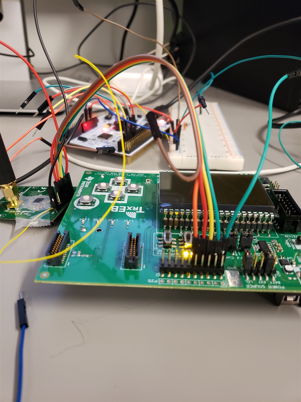
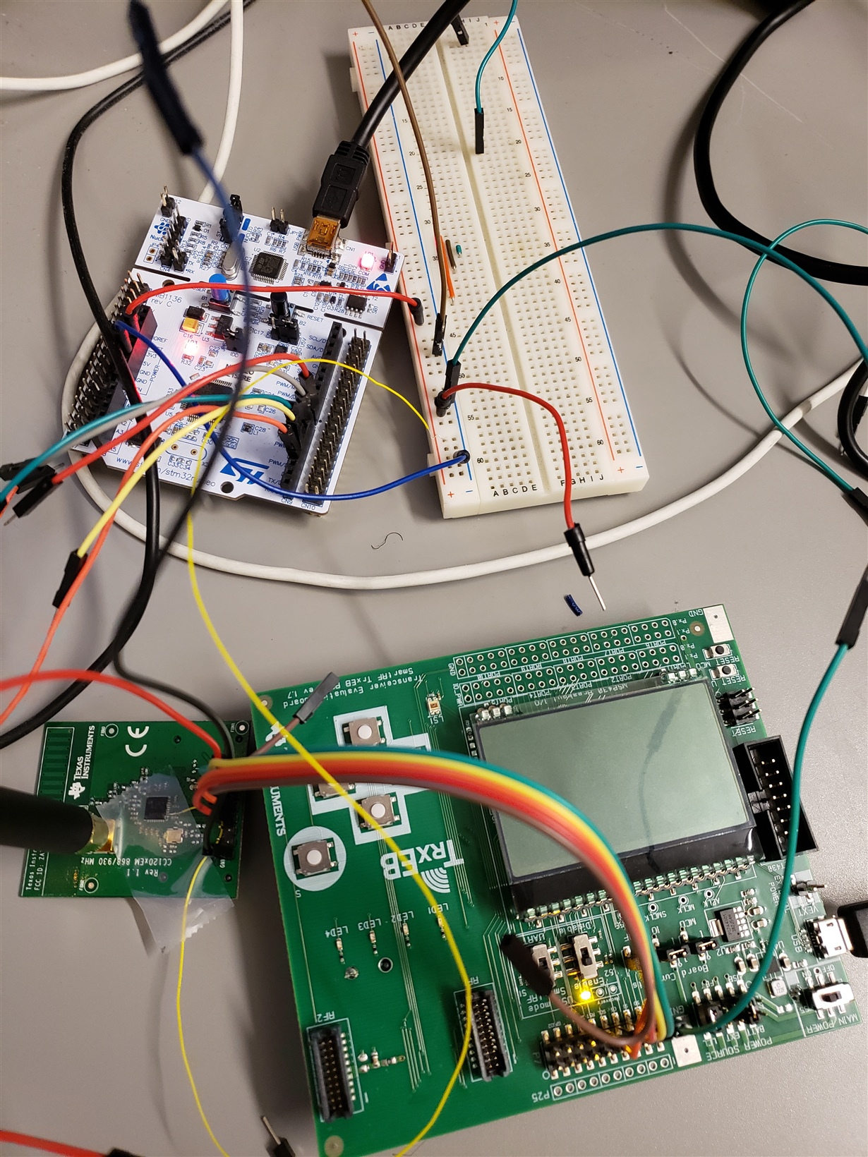
I am trying to connect a TI TexEB to the CC1200EM board to send and receive packets. In a previous post that I made, I showed a picture of the wiring between the Trx board and the CC1200EM board (see picture below). I have verified that each pin is connected properly and that I have common ground between the external microcontroller that is powering the CC1200EM board, and the TrxEB board. I have read through old forums and the previous response and reset is directly soldered to VDD and I have verified with a multimeter that it is getting power. The chip is able to be identified when I open SmartRF. 

Here is the problem: I can not send or receive packets when I am using this configuration. A picture describing the software configuration is below. I have also tried other generic configuration at different frequencies with the same result.

When the CC1200EM board is connected with the RF1 and RF2 male connector pins on the TrxEB to the P1 and P2 female connectors on the CC1200EM board, I am able to send and receive packets perfectly. When I am in the continuous TX/RX modes I am able to receive or send a signal properly, and my received signal strength (RSSI) is about -85 to -80 dBM using the external wires and about -80 dBM when using the RF to P connectors. Since the signal strength is about the same it led me to believe that it must be some sort of wiring or hardware problem between the two setups that is not allowing the packet transmissions to be received. When the board is sending packets using my wiring, it will only send a few packets before saying that the board cannot transmit (there error does not appear during continuous TX mode).

Thank you for your help and let me know if you need any clarifications. 

[For context: I would like to be able to configure the chip using an ST microcontroller, but before I can do that, I want to make sure the wiring and hardware connection works using the TI endorsed TrxEB board. Since the configuration does not work now, I do not have confidence that it will work connected to the other microcontroller.]


LMP91002: Deep sleep mode?

$
0
0

Part Number:LMP91002

I am struggling to find information on how deep sleep mode differs from standby mode. I suppose the main question is, is the control amplifier kept on in deep sleep? We want to take measurements maybe once per minute, but would be happy to have the TIA power down if possible. Minimal power is critical.

MSP430FR6047: No signal detected in up and downstream channel

$
0
0

Part Number:MSP430FR6047

Hello Eddie,

I just received my EVM430-FR6047 board this week and I have purchased 2 www.steminc.com/.../ultrasonic-flow-sensor-1mhz-send-receive ultrasonic sensors to implement a non-invasive water flow meter but I can not get the USS Design Center to detect a signal.  The Errors tab displays "No signal detected in up and downstream channel."  Obviously I've got something amiss in my configuration but I don't know what it is. I have read a response of your and you reference www.ti.com/.../slaa837.pdf but I can't access this file.  Has this file moved or been superseded? 

Thanks,

Dave

TLV320AIC3254: TLV320AIC3254

$
0
0

Part Number:TLV320AIC3254

I use this part in a production radio: CTX-10. (see commradio.com); as and audio CODEC in transmit side only.

The audio input signal chain: MIC;  PRE-AMP with constant output;  VOLTAGE DIVIDER (20k series/1k to ground); 10 uF cap coupling into the IN1_L input (mono).

The freq range is 600 - 3300 HZ (voice).  The input to the C3254 is 8. mVrms. (IN1_L).

The CODEC produces a 2-channel output using a DSP filters (both mini-DSP) to produce I and Q audio signal in quadrature (LOR and LOL).

The output signals from the C3254 are approx. 100 mVrms.

The Problem (and the reason for the large R-divider): with high input signal, the output begins to clip.  The datasheet indicates theC3254 part can accept a much higher input level

To implement MIC gain control, I need at lease 6 dB my TI FAE.

Don

CCS/TMS570LS0432: need to warm reboot from application to bootloader.

$
0
0

Part Number:TMS570LS0432

Tool/software: Code Composer Studio

In my application I implemented a Modbus register for warm-booting to the bootloader. When modbus writes a magic number to this register the application should do a warmboot into the bootloader where it waits for a command from the upgrade program on my PC.

I have not found how to successfully do a warm-boot or any other transfer to the bootloader from my application.

I've seen posts that say to set bits 14 and 15 in systemREG1->SYSECR. That did not work. My app hung looping in prefetchEntry.

Our devices will be mounted in inconvenient and oft times dangerous locations. We cannot ask our customers to push a button on the device. They must be able to do a firmware upgrade over RS-485.

Your assistance is appreciated.

    ken

looking for a bidirectional buffer to support hot plug application

$
0
0

Hi,

Customer is looking for a bidirectional buffer to support hot plug in IPC buffer,  signal frequency 33MHz.

Could you suggest a suitable part?

Thanks a lot. 

Oliver Ou

CC1200EMK-868-930: physical dimensions?

$
0
0

Part Number:CC1200EMK-868-930

What are the physical dimensions of the CC1200EMK? I'd like to fit it into a small form factor for a test but don't see dimensions in the quick start guide etc.

Is the onboard antenna sufficient for basic ISM band reception or do I generally need to use the included whip antenna?

Compiler/CC2650STK: Simple_Peripheral from ble stack isn't available to be scanned by device.

$
0
0

Part Number:CC2650STK

Tool/software: TI C/C++ Compiler

I have been working with BLE for quite some time, I have written my own services and updated simple_Peripheral program at bleStack. Everything worked fine when I was using debug mode, I can read data over my characteristics on my android application when I have my sensortag connected at debug mode.

1. But when I shutdown my code composer , sensortag still connected to laptop via cable. I can scan it.

2. I even replaced a new battery in the sensortag and disconnected it from devpack, but still I can't scan it.

How do I connect it to a button to turn it on or off as in SensorTag application at BLE_Stack????


PS: I am about to complete my project and this forum has really helped me out, I didn't know anything about sensortags and neither was I that much good in C :P Thanks.


Regards,

Faizan Shah


BQ25703A: battery bq25703a

$
0
0

Part Number:BQ25703A

In my aplication the power of th bq25703a 12V et the battery is 12V .

for the configuration the number of cell how I do it

I choose 3S (VCELL_BATPRESZ= 55% VDDA)     ?

 Thanks

Compiler: Expanding ARM335x data memory using a linker command

$
0
0

Tool/software: TI C/C++ Compiler

I'm using the ARM335X processor and CC@ 6.00.1. I'm running out of memory, and want to know how to edit the linker command file to make more memory available. #pragma causes a symbol (#) unknown error

LM5141: No output

$
0
0

Part Number:LM5141

I have built a circuit based on a WebBench design for 24-48 V input to 5 V / 5 A output using LM5141.

However, when I test it, I get no output.

Some observations:

* The low-side FET gate is driven to 5 V. No switching activity is seen. 0 V on the high-side FET's gate.

* When the EN input is asserted, the SS pin initially ramps up to 5 V (takes about 25 ms), but then drops very quickly to ~0.19 V.

* I verified 3.3 V is present on EN pin.

* I verified 5 V is present on VCC pin.

* ~4.9 V present on the boost diode (D8) cathode.

* So far I'm testing with 24 V at the VCC_48 node, and light load (no load or 56 ohms load).

I noticed this text in the LM5141 datasheet and wonder if it could be related (based on the behavior at the SS pin):

At the beginning of the soft-start sequence when SS = 0 V, the internal 20 μA softstart
current source gradually increases the voltage on an external soft-start capacitor connected to the SS pin,
resulting in a gradual rise of the FB and output voltages. The controller is in the forced PWM (FPWM) mode
when the DEMB pin is connected to VDDA. In this mode, the SS pin is clamped at 200 mV above the feedback
voltage. This ensures that SS will be pulled low quickly when FB falls during brief over-current events to prevent
overshoot of VOUT during recovery. SS can be pulled low with an external circuit to stop switching, but this is not
recommended. Pulling SS low will result in COMP being pulled down internally as well. If the controller is
operating in FPWM mode (DEMB = VDDA), LO will remain on and the low-side MOSFET will discharge the
VOUT capacitor resulting in large negative inductor current. In contrast when the LM5141 pulls SS low internally
due to a fault condition, the LO gate driver is disabled.

Any thoughts on possible root cause or next debugging steps is appreciated.

Thanks

Matt

Linux/AWR1843BOOST: SDK 3.x Data Structure Table - Where is it?

$
0
0

Part Number:AWR1843BOOST

Tool/software: Linux

Hi,

I'm trying to understand some of the changes to the code base in the version of the mmWave SDK compatible with the AWR1843 - SDK v3.01.01.02.

Based on the modifications to the code in DataHandlerClass.cpp, the Data Structure that had previously been used to package the Detected Object data mmwData.objOut = {x, y, z, rangeIdx, dopplerIdx, peakVal} has changed.

It now appears that the new data structure is of the form: mmwData.newObjOut = {x, y, z, velocity} with a separate location for the intensity value in mmwData.sideInfo = {snr, noise} where the snr value gets converted to an intensity measure according to the following calculation:

RScan->points[i].intensity = (float) mmwData.sideInfo.snr / 10.0;

Q1: Is the velocity value in m/s or is it still in the form of the original dopplerIdx value that needs to be converted to m/s?

Q2: Where can I find documentation for this new Data Structure released for SDK v3.01.01.02? I'm looking for something similar to pdf that be found at the following link (also attached):

e2e.ti.com/.../mmw-Demo-Data-Structure_5F00_8_5F00_16.pdf

(Please visit the site to view this file):

ADS8363EVM: Interfacing to the TMS320C6748 (C6748 LCDK)

$
0
0

Part Number:ADS8363EVM

Hello,

I am trying to interface the TMS320C6748 to the ADS8363 EVM using the SPI1 pins. I want to utilize the enable pin for handshaking with the ADC but can not find it on J15 or J16 headers. I also need a way to trigger the RD and CONVST bits on the ADS8363 but can not figure out how to do so. My thought process so far is to use one of the CS pins as a GPIO that will toggle the RD and CONVST bits right before I actually transmit the data. I am not looking for an in depth explanation on how to do this but a simple description on the process would be extremely helpful. Thank you. 

Viewing all 262198 articles
Browse latest View live


Latest Images

<script src="https://jsc.adskeeper.com/r/s/rssing.com.1596347.js" async> </script>