Quantcast
Channel: Forums - Recent Threads
Viewing all 262198 articles
Browse latest View live

Frequency Slope

$
0
0

Part Number:IWR6843

Tool/software: WEBENCH® Design Tools

Hey there,

1.)

In the datasheet of the IWR6843 the Ramp rate is given by 266 MHz/μs.

Then I found the following (Source: mmwave_sdk_03_01_01_02\packages\ti\control\mmwavelink\docs\doxygen\html\structrl_profile_cfg__t.html)

rlInt16_t freqSlopeConst
 Ramp slope frequency,
For 77GHz devices (76GHz to 81GHz):
1 LSB = (3.6e6 * 900) / 2^26 = 48.279 kHz/uS
Valid range: -2072 to 2072 (Max 100MHz/uS)
For 60GHz devices (57GHz to 64GHz):
1 LSB = (2.7e6 * 900) / 2^26 = 36.21 kHz/uS for 60GHz devices
Valid range: -6905 to 6905 (Max 250 MHz/uS)

And finally the mmWave Sensing Estimator says: Slope only can be 100MHz/µs or less.

So what is correct?

2.)

Another question about the mmWave Sensing Estimator: What is the frequency slope constant?

Thank you in advance!

Nicolas


LM74610-Q1: Timing of Vcap does not match the expected value

$
0
0

Part Number:LM74610-Q1

Hello,

The circuit we are designing is the input to a DCDC module. We have used the LM74610-Q1 in the return path to protect from reverse polarity. As of now the circuit is as it is shown in the schematic picture attached.

When checking the voltage drop across the Vcap capacitor the timing does not match the behavior described in the datasheet. The datasheet says that the fall time should be 5.7 seconds and the rise time should be 0.1175 seconds when using a 4.7uF capacitor. As it can be seen in the picture we get 1.22 seconds fall time and 0.034s rise time. Giving a 97.3% duty cycle instead of the 98% that the datasheet says.

Ambient temperature is 25C and the IC gets around 37C after running 10 minutes with 20A through the transistor (the model is IAUT240N08S5N019ATMA1).

In one of the boards we discovered that the timing was 500ms fall time and 40ms rise time, giving a 92.3% duty cycle. This was solved by changing the LM74610-Q1.

What could be the cause of the wrong timing? What could have caused that the IC broke?

Thanks in advance

Best regards, Inigo

(Please visit the site to view this file)

UCD3138A: BIST

$
0
0

Part Number:UCD3138A

Is there any document to specify the BIST capability of the UCD3138A?

From the UCD3138 Technical Reference Manual I can see there are 4 registers DPWM BIST Status Register (DPWMBISTSTAT). There's also an Enable bit for BIST (BIST_EN) in Loop Mux Test Register (LOOPMUXTEST) and a flag to check BIST complete status (BIST_COMP).

I need to investigate BIST capabilities from this micro and I can't find any information or documentation. I'm also trying to find programming guide and I can't find it either. I need to know all CPU registers and instruction set.

Thanks,

Gianpiero.

BQ34110: BQ34110 : Parameters for NiMh

$
0
0

Part Number:BQ34110

Hello,

I'm starting with the bq34110 with the corresponding eval board.

Does anyone have a set of parameters for a NiMh battery (I'm using a 24V 10Ah Nimh battery) ? Or, at least, a example config file for NimH ?

Thanks in advance,

E. Tillol

MAX232: MAX232 overheat

$
0
0

Part Number:MAX232

Hello people,

How are you?

I'm using the MAX232DWR part number in my project to  connect in a smart card reader, according attached file.

Sometimes during card reading operation, occurs an overheat in MAX232 IC.

Why is it occuring? Can you help me to resolve this issue?

Best Regards

AM6548: SGMII Type

$
0
0

Part Number:AM6548

Hi Processors Team,

Quick question, is the SGMII on the AM6548 LVDS or CML based?

Thanks,
Barend

BQ27742-G1: IC fails to respond to I2C commands after a protection mode is enabled

$
0
0

Part Number:BQ27742-G1

If the output of pack is shorted (of some other protection state), it can no longer be polled for that state or communicated with via the I2C bus.  Essentially if anything occurs to turn off the FET's and PACKP goes to 0VDC, the bus won't respond.  Our design follows the reference design in the TRM and we aren't using PACKP as reference for our pull-up.  We also still have VPWR applied.  Is this normal behavior?

Thanks 

Linux/BEAGLEBK: Errors at boot thru sd card on beaglebone black

$
0
0

Part Number:BEAGLEBK

Tool/software: Linux

HI

I am trying to make sd card for booting.

i am not using pre-built image because i need to change linux source code.

https://www.digikey.com/eewiki/display/linuxonarm/BeagleBone+Black

As described in the site above, I installed u-boot source, kernel source, file system.
and then I compiled u-boot source and kernel source

as instruction, I tried to setup sd card.
I think I'm proceeding to umount normally.

but there are some errors when i insert sd card into sd card holder and power on the beaglebone black
I dont know what is wrong.
could you let me know about errors and how to resolve them?
the errors is as blow


Note that.

compiler :

releases.linaro.org/.../gcc-linaro-7.3.1-2018.05-x86_64_arm-linux-gnueabihf.tar.xz


u-boot

bootloader download path : github.com/.../u-boot
git checkout v2018.09-rc3 -b tmp
uboot patch file : https://rcn-ee.com/repos/git/u-boot-patches/v2018.09-rc3/0001-am335x_evm-uEnv.txt-bootz-n-fixes.patch

kernel

kernel version : 4.14


large current for power pulse

$
0
0

HI TI guys:

      Recently ,we have a case to use a power Spc that need output a pulse with 5V programmed & 9.1A  

and 1ms pulse width is fit to me . 

   Did TI ever design a module board or some circuit with validated .

   Thanks guys

TLC59116: Standby mode entry

$
0
0

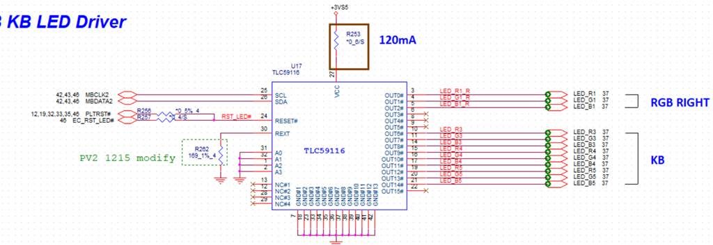
Part Number:TLC59116

Hi,

We encounter an issue to enter Standby Mode with schematics as below.  THe power consumption we fot from Vcc pin is as below, and we don't understand why it become bigger while RESET pin is low.  Anything you would suggest us to check?  THanks!


Reset pin High : power consumption is 80mw

Reset pin Low : power consumption is 115mw

THanks!

Antony

DCA1000EVM: The lvds data obtained by running the lua script is empty, what should I do?

$
0
0

Part Number:DCA1000EVM

I am running with a script and the DATA_TRAN_PRG light from the DCA1000EVM is lit green, but this light is not flashing. And I found the file save path on the PC and found that all the files collected are 0kb. What should I do? A screenshot of the script and data collection files is listed below.Except for running this script, what configuration do I need to do about iwr1642?

BQ24192: PCM Recommendation

$
0
0

Part Number:BQ24192

Hello TI power management forum,

I have a question concerning lithium ion battery protection. We're developing a charger product derived from the BQ24192& BQ27531 typical application schematic (bq27531-g1.pdf figure 12). Our application will use five 18650 Li-Ion cells in parallel (in other words, a 1s5p configuration). We were wondering if TI had any recommendations for battery safety provisions beyond what's reflected in the typical application schematic. We are considering using raw 18650 cells without an integrated PCM (protection circuit module) or battery-leveling circuit.

Any comments about the BQ24192's suitability in a 1s5p raw Li-Ion cell application would be appreciated.

Thanks!

Jeffrey Dowell

TSW30SH84EVM: How to control two boards using one GUI (TSW308x_v2p2)

$
0
0

Part Number:TSW30SH84EVM

Two TSW30SH84EVMs are used in a project. I want to control both boards using the same GUI. As the USB port is detected automatically, I am not able to make any selections. So is there a solution for this application?

CCS/MSP430F5529: MSP430F5529

$
0
0

Part Number:MSP430F5529

Tool/software: Code Composer Studio

Has anyone connected the MSP430F5529 to an eCom LSM303 Compass for the SPI? Or any similar device?

Will the following connections work?

MSP430F5529               TO        eCom LSM303agr or LSM303AH

UCA0   SOMI     P3.4     TO         Pin  4     SDI/O                                         

UCA0   SIMO     P3.3     TO         Pin  4     SDI/O          Note both SIMO and SOMI go to Pin4

UCA0   SCLK    P2.7      TO        Pin  7     SCLK

                            P3.5       TO        Pin  2     CS_ACC

Would these I2C connections work?

 UCB1SDA       P4.1     TO         Pin  4     SDI/O    

UCB1SCL       P4.2      TO         Pin  7     SCLK

                          P3.5      TO         Pin  2     CS_ACC

jerry@game-finder.com

BT-MSPAUDSOURCE-RD: Connectivity of ADC TLV320ADC3101 with PurePath Studio

$
0
0

Part Number:BT-MSPAUDSOURCE-RD

Hi,

I have a BT-MSPAUDSOURCE board and want to program its ADC TLV320ADC3101 using PurePath Studio Graphical Development Environment, but it seems PurePath only accepts as device  the set USB-MODEVM and TLV320ADC3101EVM boards, connected one to another.

Is there a way to use BT-MSPAUDSOURCE-RD as a recognizable hardware device of PurePath Studio through USB interface? 

Or could I use PurePath Studio to program ADC TLV320ADC3101 (present in  BT-MSPAUDSOURCE-RD) directly through its I2C interface?

Does the content transmitted at USB interface of PurePath is aimed at communicating only with an MSP430 microcontroller, or could it be used, with the aid of an USB-to-I2C adapter, as I2C master of ADC TLV320ADC3101 (in that case i would connect I2C signals of the adapter and ADC)?   

If nothing works, how could I transfer the source code generated by PurePath to my ADC TLV320ADC3101? Is it mandatory to use USB-MODEVM and TLV320ADC3101EVM boards?

Best wishes,

Newton Bomeisel Cardoso


TINA/Spice/TPS62125: Simulation of inverting buck-boost topology

$
0
0

Part Number:TPS62125

Tool/software:TINA-TI or Spice Models

Hi, 

I am considering using the TPS62125 in an application requiring generation of -10V from +10v using the inverting buck-boost topology detailed in this app note:

However, in simulating this circuit with Tina-TI, I am not getting anything like the outputs expected. The attached schematic is the same as the test circuit shown in Fig. 16 of the above app note (which produces -5V from +5V input), but as you can see from the attached simulation results, the output is nothing like a regulated -5V.

It would seem like I am missing something fundamental - any ideas as to what it might be?

Thanks,

Best regards,

Anand.

(Please visit the site to view this file)

ADS1293EVM: ADS1293 spi interface MSP430 problem

$
0
0

Part Number:ADS1293EVM

Hello,

I would like to ask you about my trouble with launching demo3 from "MSP430 Interface to ADS1293 Code Library". It always stuck on this while. I would like to send real time ecg data from ADS1293 to MSP430F5529. I will appreciate any help with this trouble. Do you know any other codes for interfacing these devices. I will be glad for any inspiration how to solve the communication.

I am not able to display any data as well. I will also appreciate any advice how to display these data.

Thank you,

Daniel

RTOS/CC3220MODA: Help with TIRTOS API for Eample the Function pthread_cancel

$
0
0

Part Number:CC3220MODA

Tool/software: TI-RTOS

I am trying to become familiar with the working of the network terminal (network_terminal_CC3220SF_LAUNCHXL_tirtos_ccs) example for the CC3220 Launchpad.

I am not able to find documentation on functions managing the P2P connection.

For example the line "pthread_cancel(p2p_connectThread);" which is at about 1594. It may be at a some what different line number in the original code since I have been adding some comments and print statements into my copy.

Would appreciate a pointer to documentation that will get me up to speed on the pthread functions.

Thanks,

(Forrest) Lee Erickson

BQ20Z65-R1_BQEVSW-SW: Can't find the file to download for the bqevsw-sw tool

$
0
0

Part Number:BQ20Z65-R1_BQEVSW-SW

I have a system with a bq24735 charge controller chip on the RRC-PMM240 battery management board, and a bq20z65 is the fuel gauge chip inside the RRC2020 smart battery pack.

I am not able to talk to these devices via bqStudio. Also, the bq20z65-R1-bqevsw-sw software tool is not available from the download page on ti.com.  I'm using a TI EV2400 interface between my laptop and system, with the SMBUS port connected to VCC, SDA, SCL and GND of the PMM240 board.

How can I get all this working?

Thanks,

Carl Olen

TIDA-00778: Suppy Current for gate driver

$
0
0

Part Number:TIDA-00778

Dear TI Experts:

When we design an external power supply for the gate driver, we need to determine the maximum current output of the power supply.

For TIDA-00778, 15-V supply current for gate driver is 50 mA (max), as shown in Table 2 on Page 11.

But in Section 1.4.3.1, we can find I_HO_DR=1.47A and I_LO_DR=1.53A.

So, could you kindly show me how to determine the 50 mA (max), shown in Table 2 on Page 11.

Look forward to hearing from you~

Best Wishes,

Tang Han

Ps.

For TIDA-00472, 15-V supply current for gate driver is 50 mA (max), too, as shown in Table 1 on Page 2.

But in Section 4.3.1, we can find I_HO_DR=1.05A and I_LO_DR=1.09A.

Viewing all 262198 articles
Browse latest View live


<script src="https://jsc.adskeeper.com/r/s/rssing.com.1596347.js" async> </script>