Quantcast
Channel: Forums - Recent Threads
Viewing all 262198 articles
Browse latest View live

CCS/CC256XQFNEM: Only SPPDemo project Opens the Bluetooth Stack without error, but it can not pair

$
0
0

Part Number:CC256XQFNEM

Tool/software: Code Composer Studio

I have purchased   eval kit MSP-EXP430F5438 Experimenter Board and two different version of dual Bluetooth extension modules, one of the is CC256xQFNEM and the other is CC2564MODAEM.

I have install CCs-8.3 version and MSP430 Compiler v 4.15.

The above builds without errors all project examples for TI dual-mode Bluetooth® stack on MSP430 MCUs CC256XMSPBTLESW Version v.15 R2 ( updated with patch for the CC256x devices v.1.7.

and added to BTVS.c the follwing lines - they make no difference) 

#define __SUPPORT_CC256XB_PATCH__
//#define __CC256XBH__

My problem is that only SPPDemo can open the TI Bluetooth stack without any errors. However it can not pair to anything and it is invisible to any Bluetooth enabled devices from Android nor windows and Apple.

Can anybody please shed some light on how to get those TI example working on the above eval boards?

Do I need a different eval board, do I need to fix old library - TI please speak up what am I doing wrong ..what is the right way to use your products?

The Wiki pages for the stack library examples are not helping to resolve it at all.

OpenStack().
Bluetooth Stack ID: 1
Device Chipset: 4.0
BD_ADDR: 0xD4F5135E1BC4

the other examples gives the following errors:

HIDemo:

OpenStack().
Stack Initialization Failed: -4.
Unable to open the stack.

HTPDemo:

OpenStack().
Error - BSC_Initialize returned -4.
Unable to open the stack.

Thank you,


CC2640R2F: Why device turn to Non-Resolvable Private Address?

$
0
0

Part Number:CC2640R2F

Dears

Customer MP 5K pcs product base on CC2640R2F, and ~30pcs customer peripheral product cannot connected with customer central product. However this ~30pcs customer peripheral product can be connected by smartphone BT tools.

After investigation, we found the MAC address on such ~30pcs peripheral product are Non-Resolvable Private Address.  We guess this is the reason for fail  connection with customer central product, which set connection with peripheral product by using 1 to 1 Public Address 

Do you think if Non-Resolvable Private Address is the real cause for connection fail? Why there are ~30pcs peripheral product are Non-Resolvable Private Address?

AM5728: TIDL outputs not determistic

$
0
0

Part Number:AM5728

Hi,

I am running the TIDL imagenet example from the processor SDK 05.02.00.

Although I run it with a static image the outputs vary quite a lot. Below you can see that within 10 consecutive runs the output for e.g. the top 1 class varies between 101 and 168.

Should it not be determistic?

root@am57xx-evm:/usr/share/ti/tidl/examples/imagenet# ./imagenet -f 10
Input: ../test/testvecs/input/objects/cat-pet-animal-domestic-104827.jpeg
======================================
1: tabby,   prob = 134 (52.55%)
2: Egyptian_cat,   prob = 54 (21.18%)
3: tiger_cat,   prob = 45 (17.65%)
======================================
1: tabby,   prob = 136 (53.33%)
2: Egyptian_cat,   prob = 68 (26.67%)
3: tiger_cat,   prob = 34 (13.33%)
======================================
1: tabby,   prob = 148 (58.04%)
2: Egyptian_cat,   prob = 60 (23.53%)
3: tiger_cat,   prob = 24 (9.412%)
======================================
1: tabby,   prob = 150 (58.82%)
2: Egyptian_cat,   prob = 62 (24.31%)
3: tiger_cat,   prob = 26 (10.2%)
======================================
1: tabby,   prob = 140 (54.9%)
2: Egyptian_cat,   prob = 61 (23.92%)
3: tiger_cat,   prob = 27 (10.59%)
======================================
1: tabby,   prob = 138 (54.12%)
2: Egyptian_cat,   prob = 61 (23.92%)
3: tiger_cat,   prob = 27 (10.59%)
======================================
1: tabby,   prob = 168 (65.88%)
2: Egyptian_cat,   prob = 30 (11.76%)
3: tiger_cat,   prob = 30 (11.76%)
======================================
1: tabby,   prob = 153 (60%)
2: Egyptian_cat,   prob = 59 (23.14%)
3: tiger_cat,   prob = 23 (9.02%)
======================================
1: tabby,   prob = 157 (61.57%)
2: Egyptian_cat,   prob = 55 (21.57%)
3: tiger_cat,   prob = 19 (7.451%)
======================================
1: tabby,   prob = 101 (39.61%)
2: Egyptian_cat,   prob = 101 (39.61%)
3: tiger_cat,   prob = 31 (12.16%)

BQ76PL455A-Q1: The voltage of cell#12 is always higher than the actual value

$
0
0

Part Number:BQ76PL455A-Q1

Hi,

We use our own designed circuit board to manage 26-cell. Each board manage 13-cell.

We have a issue that is voltage of Cell #12 always higher then the actual value, and Cell #13 always lower then the actual value.

Board #1 and board #2 are the same. Please see following picture.

Do you have any recommend?

Best Regards,

Aaron

TINA/Spice/LM5155: LM5155 Encrypted Spice Model can't be Imported to TINA for Simulation

$
0
0

Part Number:LM5155

Tool/software:TINA-TI or Spice Models

Spice model for LM5155 is encrypted, importing the model to TI Tina does not work. How can I import this model to TI Tina and run simulation with it?

Logic solution

$
0
0

Hello

             Do we have logic to meet below truth table ? Thank you. 

Function table

Input

Output

A

B

Y

0

0

0

1

0

1

0

1

Invalid

1

1

1

CCS/TMS320F28374S: How much work required to move project from 2806x to 28374S

$
0
0

Part Number:TMS320F28374S

Tool/software: Code Composer Studio

I have developed a relatively complex system based on 28069 mcu, lots of features, such as CLA, DMA, USB, ePWM, usb bootloader etc.  are used.

Is it easy to transfer the code from a existing 28069 project to 28374S? 

Compiler/TMS320C6713B: boot table can't be loaded corectly

$
0
0

Part Number:TMS320C6713B

Tool/software: TI C/C++ Compiler

Hi:

    I used CCS 3.3.83.20 to build my project and use hex6x to make the boot table. When I load the boot table with my own secondary boot loader, it crashed.

    I checked the map file, found one section's length is not multiple of 4,  and the next section's begin with multiple of 4, which will cause 2 bytes placeholder(filled zero) in the boot table.

    When I load the boot table, the 2 bytes of zero will be used as part of the next section's length, so it's wrong .

    But, one of my colleague used CCS 3.3.38.xx(I forgot) to build my project, all the section's length are multiple of 4. When I make boot table with his .out file, it works well.

    So, is there any diffrence between the 2 CCSs in compiler(6.1.x and 6.0.x)?

    Can I get some documents or datasheet about this?

    Should I make diffrence secondary boot loader for the diffrence CCS?    

    Thank you very much!


I also checked the two spru186 of this 2 CCS, they are same in boot table file format, as this:

The boot table format is simple. There is a header record containing a 4 byte field that indicates where the boot loader should branch after it has completed coping data. After the header, each section that is to be included in the boot table will have the following:

1. 4 byte field containing the size of the section

2. 4 byte field containing the destination address for the copy

3. The actual data to be copied Multiple sections can be entered; a termination block containing a 4 byte field of zeros follows the last section.


Compiler/TMS320F28379D: memcpy for >256 words does generate RPT || PREAD but does lcr memcpy => how to avoid

$
0
0

Part Number:TMS320F28379D

Tool/software: TI C/C++ Compiler

Hi,

in my code I have to copy some quite big structs, some of them are bigger than 256 words. For the smaller ones the expected combination of RPT and PREAD is generated and this performs well. For the bigger structs a call to memcpy (lcr memcpy) is generated which takes more than 10 times longer to execute.

I read in the compiler manual in the section about --rpt_threshold that under some conditions multiple RPTs may be generated, but whatever options I tried I never got this. Is there a way to force the compiler to generate as much RPTs it takes and avoid memcpy?

I can get it to work when I put multiple lines of memcpy in the code an copy the struct manuall in sections this way. But as my code is generated by Simulink this is not a good solution.

I use version 18.1.4.LTS.

Thanks,
Thomas.

TXB0106: TXB0106 Voltage shift isn't correct between 3.3V and 5V

$
0
0

Part Number:TXB0106

Hi,

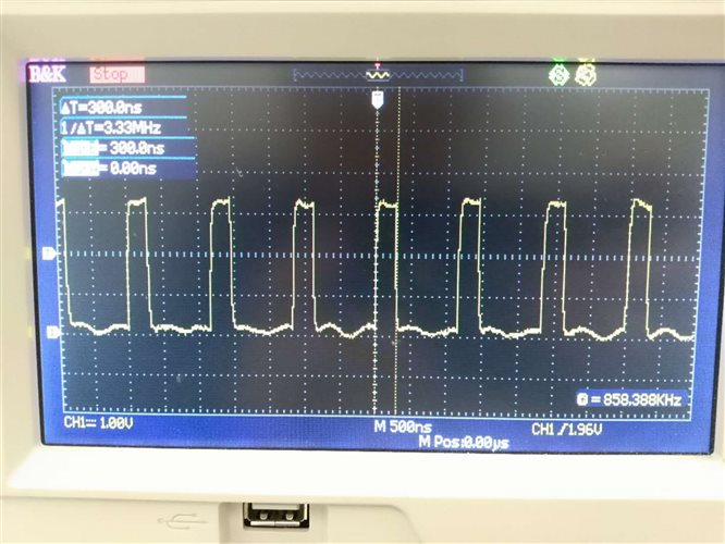
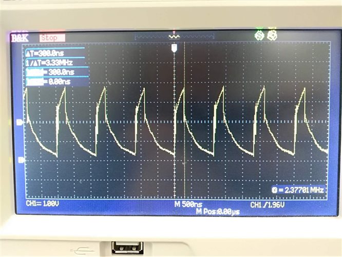
I used the TXB0106 to do the voltage shift between 3.3V and 5V. But the waveform isn't correct. I appreciate if you can give me some suggestions. Thanks.

Regards,

John

3.3V side waveform

5V side waveform

Schematic

CCS/TMS320F28069: How to use Duty Cycle to control motor using InstaSPIN on F28069?

$
0
0

Part Number:TMS320F28069

Tool/software: Code Composer Studio

Hello, 

For my project, I am using a custom board with TMS320F28069 and DRV8305 with 6 FETs to control an ACIM. I have verified all parameters using Lab 2c. V18 Motorware is not working for me, the left pane is never in, but I am able to run the labs using CCS v9. 

I want to control the RPM of this motor by a duty cycle signal. This would be done using a square-wave duty cycle generator, going as input to the TMS320F28069. I found out on the:  http://www.ti.com/lit/ug/tiduak1/tiduak1.pdf   (BLDC Reference design for ESC control) how the TMS320F28027F communicates with a flight controller interface using the eCAP modules which go as Speed reference to the controller. For the TMS320F28069, how do I do this? I know that there are 3 eCAP modules available for the F28069, but it mentions that I have to configure the pin. Can someone please explain, where in the Hal.c file, do I do the configuration? Is it in ' void HAL_setupGpios(HAL_Handle handle) ' ? Will it help if I use HRCAP (High ResolutionCAP) rather than eCAP (enhancedCAP) to read the duty cycle input? I am using the 100pin PZP package for the 28069, where Pin # 64 is the eCAP pin, if I have the signal going in here, it should work right? I am still learning about the InstaSPIN control and getting used to CCS. I have a LaunchXL-F28069 launchpad and BoostXL-DRV8305 booster pack to do my testing and evaluation. It should be the same code that goes in this combination that would eventually go in my custom board. So I am trying to have a board that, once it is powered-on, it goes into motor control and according to the DutyCycle input, it varies the motor speed. I've narrowed it down to the following 3 steps that I would be following:

  1. Use the launchpad and booster pack combo to identify motor parameters and do current and speed tuning of the controller to maximize torque using the labs.
  2. Somehow, get this tuned control to work with external duty input to control motor RPM.
  3. Export the code to the custom board.

If I could get some clarity on my doubts (step 2), that would be great. 

Thanks!

TMS320F280049C: ARM-10 JTAG nRESET connection recommendation

$
0
0

Part Number:TMS320F280049C

Hi, I am looking for a recommendation on how to connect the nRESET pin of the ARM-10 JTAG header to a design with multiple F280049C devices. Should it be connected at all? Please advise, thanks.

Bill

TL431: TL431 w/ buffered output

$
0
0

Part Number:TL431

Hello,

Background:

I am designing signal conditioning circuits that level shifts from 3.3 or 5.25V to 15V and from 15V to 3.3 or 5.25V (for interfacing between PXI digital I/O and a unit under test (UUT)). The connections will be configurable within the product, so I want to protect the inputs of my circuitry against over-voltage in case incorrect connections are made. On the low voltage side (3.3 or 5.25), I am using an input resistor (10k) connected to the anode of a low capacitance diode (2pF) with collector tied to the 3.3 or 5.25 rail. Assuming worst case of all inputs pulled to +15V, the 1.15mA per input adds up quickly for the many channels I'm using.

I want to use the TL431IB for its accuracy, but need to buffer its output to sink < 200mA.  So, I have designed a simple NPN/PNP push-pull buffer w/ a 10uF output cap as shown here.

R2 (100 ohms) is used to allow limited control of the output when the base/emitter junctions are "off".

Based on the TL431 data sheet, I believe the output cap in series with R2 is OK.

Also, The JP11, R3 & R5 resistors are to allow for choosing the 3.3 or 5.25V output.

Question:

Are there any "red flag" concerns to which I should be paying attention?


Including for example: looking at data sheets for some regulators, diodes are recommended for certain conditions (e.g. turn off), such as shown in the following excerpt from the LM117 datasheet. Would this be a concern for my circuit?

Any suggestions or warnings will be appreciated.

- James

CC3200: CC3200

$
0
0

Part Number:CC3200

Hi,

I have CC3200Sensortag and connecting through android application Simple SensorTag, It is connected to Wifi of Mobile and also showing in the App to connect, Once it goes through the connecting by App it is automatically disconnected from Wifi hence don't show in the App again. I tried with resetting but also the same problem.

Please any idea.

Regards,

Nadeem

PCA9306: IBIS module select

$
0
0

Part Number:PCA9306

Hi team,

My customer want to use the IBIS module in the web.

They need 3.3V to 1.8V, can you help to indicate the difference between two modules as below:

1. [Model] PCA9306_IO_18_S Model_type  Series_switch

2. [Model]PCA9306_IO_18,Model_type  Terminator

Which module can be used for the 3.3V to 1.8V application?

Lacey

Thanks a lot!


IWR6843: Antenna design

$
0
0

Part Number:IWR6843

For our applications we are considering our antenna design, so we need to better understand the following information:

  • Maximum input power of the receivers
  • Input 1dB compression point of the receivers
  • Input IP3
  • Data about the spurious emission and harmonics of the transmitters
  • Matching of the transmitters (S11)
  • Matching of the receivers (S11)
  • Isolation between the TXs and all the RXs
  • Isolation between adjacent receivers and isolation between other receivers (not including the adjacent one) 

Moreover we would like to get these other details

  • Gain and phase mismatch between the receivers

Thanks

BEAGLEBN: Using eMMC failed.

$
0
0

Part Number:BEAGLEBN

Dears:

Customer uses our BBB EVM to evaluate the performance of AM3358.

However, using eMMC failed, and pls. kindly provide the below website’s link?

Since these link can not download.

TLV320ADC3101: Is there any driver under Linux system about tlv320adc3101?

DAC8742HEVM: read/write the Low Level Configuration in GUI

$
0
0

Part Number:DAC8742HEVM

Hi,

After the discussion of below post, I can read and write the PAFF in High Level Configuration of GUI, in DAC8742HEVM.  But in Low Level Configuration, I didn't see the register value of Reg_0x23 and Reg_0x24 is what I read and write. How to write/read date to PAFF through register? Because I will access DAC8741H through SPI of MCU in customer's project, I would like to know how to configure registers for PAFF write and read.

Thanks.

https://e2e.ti.com/support/data-converters/f/73/t/752474

MSP430G2553: LPM4 settings - high sleep current

$
0
0

Part Number:MSP430G2553

Hi All,  

I have some code which has high sleep current during LPM4.   I have made a branch that ripped everything out except   a)  setting all pin assignments,  b)  setting some clock, ADC, UART settings,  c) going to LPM4 sleep   So basically, system turns on, does some housekeeping and goes to sleep.

The high sleep current in LPM4 -may- be hardware-related but I need to ensure that the software is bulletproof before suggesting that.

Here is a code snippet.   All the pin assignments (P1DIR, P1REN,P1OUT, etc.) are set to an output high or low, no resistor enable.  All the port select settings (PSEL, P2SEL, P3SEL, etc.) are set to 0, so the port are all general purpose I/O.

///////////////////////////////////// code snippet ////////////////////////////////////

DCOCTL = 0; // Select lowest DCOx and MODx settings

BCSCTL1 = CALBC1_1MHZ; // Set DCO

DCOCTL = CALDCO_1MHZ;

// disable UART
UCA0CTL1 |= UCSWRST; // **DEACTIVATE USCI state machine**
IE2 = 0; // disable all USCI_A0 interrupts

// disable ADC conversion
ADC10CTL0 &= ~ADC10IE;
ADC10CTL0 &= ~ADC10ON;
ADC10CTL0 &= ~REFON;
ADC10CTL0 &= ~ADC10SHT_2;
ADC10CTL0 &= ~SREF_1;

// stop watchdog timer
WDTCTL = WDTPW + WDTHOLD; // Stop WDT - also resets clock to SMCLK

__bis_SR_register(LPM4_bits); // Enter LPM4 - NO global interrupts enabled


///////////////////////////////////// end of code snippet ////////////////////////////////////

Is there anything wrong with doing the above?   Anything else I should do before going to LPM4? 

My understanding is that LPM4 basically disables everything - clocks, etc. so really those settings shouldn't matter.  Does anyone have any code references for entering LPM4?

Thank you!

Viewing all 262198 articles
Browse latest View live


<script src="https://jsc.adskeeper.com/r/s/rssing.com.1596347.js" async> </script>