Hi,
I am working on the F28335 Peripheral Explorer board. I am trying to run the ADC in the continuous run mode at the maximum sampling rate of 12.5MSPS.
I think that i have programmed the ADC in the correct configuration and i do get a correct sampled input waveform at low sampling rates. The input waveform is a 40KHz sawtooth waveform.
However at high sampling rates such as of 8.3MSPS (HSPCLK = 150MHZ, ADC_CLKPS = 3, ACQ_PS = 1)the sampled waveform looks something like this.
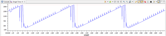
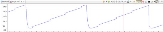
and for even higher rate i.e 12. 5MHZ (HSPCLK = 150MHZ, ADC_CLKPS = 3, ACQ_PS = 0) the wave form looks like this
To view this graph in code composer studio I am using the code from the Example_2833x AdcSeq_ovdTest.c which basically uses the main loop to look for interrupt from the ADC after every seven conversions and then copies the data into the memory buffer. The contents of the memory buffer i then display using single time plot in the code composer studio .
My understanding of these observations is that at the higher ADC sampling rates the CPU is unable to read the ADC registers before they are overwritten.
This implies that the F28335 can not be used with ADC running at 8.3MHz or higher smapling rates. At least not with this code. This would mean that will have to go into assembly?I read in another post on this forum that this should not be the case.
Can anybody please help me in this regard.?
The detailed code is given below
void main(void)
{
Uint16 i;
Uint16 array_index;
//--- CPU Initialization
InitSysCtrl(); // Initialize the CPU (FILE: SysCtrl.c)
InitGpio(); // Initialize the shared GPIO pins (FILE: Gpio.c)
InitPieCtrl(); // Initialize and enable the PIE (FILE: PieCtrl.c)
InitWatchdog(); // Initialize the Watchdog Timer (FILE: WatchDog.c)
//--- Peripheral Initialization
InitAdc(); // Initialize the ADC (FILE: Adc.c)
InitEPwm(); // Initialize the EPwm (FILE: EPwm.c)
InitECap(); // Initialize the ECap (FILE: ECap.c)
AdcRegs.ADCTRL1.bit.ACQ_PS = 1; // Sequential mode: Sample rate = 1/[(2+ACQ_PS)*ADC clock in ns]
// = 1/(3*40ns) =8.3MHz (for 150 MHz SYSCLKOUT)
// = 1/(3*80ns) =4.17MHz (for 100 MHz SYSCLKOUT)
// If Simultaneous mode enabled: Sample rate = 1/[(3+ACQ_PS)*ADC clock in ns]
AdcRegs.ADCTRL3.bit.ADCCLKPS = 3;
AdcRegs.ADCTRL1.bit.SEQ_CASC = 1; // 1 Cascaded mode
AdcRegs.ADCTRL1.bit.CONT_RUN = 1; // Setup continuous run
AdcRegs.ADCTRL1.bit.SEQ_OVRD = 1; // Enable Sequencer override feature
AdcRegs.ADCCHSELSEQ1.all = 0x2; // Initialize all ADC channel selects to A0
AdcRegs.ADCCHSELSEQ2.all = 0x2;
AdcRegs.ADCCHSELSEQ3.all = 0x2;
AdcRegs.ADCCHSELSEQ4.all = 0x2;
AdcRegs.ADCMAXCONV.bit.MAX_CONV1 = 0x7; //
DelayUs(5000);// Wait 5ms before using the ADC
//--- Enable global interrupts
asm(" CLRC INTM, DBGM");
for (i=0; i<BUF_SIZE; i++)
{
SampleTable[i] = 0;
}
// Enable global interrupts and realtime debug
//--- Main Loop
while(1)
{
array_index = 0;
for (i=0; i<(ADC_BUF_LEN/16); i++)
{
// Wait for int1
while (AdcRegs.ADCST.bit.INT_SEQ1== 0){}
AdcRegs.ADCST.bit.INT_SEQ1_CLR = 1;
SampleTable[array_index++]= ( (AdcRegs.ADCRESULT0)>>4);
SampleTable[array_index++]= ( (AdcRegs.ADCRESULT1)>>4);
SampleTable[array_index++]= ( (AdcRegs.ADCRESULT2)>>4);
SampleTable[array_index++]= ( (AdcRegs.ADCRESULT3)>>4);
SampleTable[array_index++]= ( (AdcRegs.ADCRESULT4)>>4);
SampleTable[array_index++]= ( (AdcRegs.ADCRESULT5)>>4);
SampleTable[array_index++]= ( (AdcRegs.ADCRESULT6)>>4);
SampleTable[array_index++]= ( (AdcRegs.ADCRESULT7)>>4);
while (AdcRegs.ADCST.bit.INT_SEQ1== 0){}
AdcRegs.ADCST.bit.INT_SEQ1_CLR = 1;
SampleTable[array_index++]= ( (AdcRegs.ADCRESULT8)>>4);
SampleTable[array_index++]= ( (AdcRegs.ADCRESULT9)>>4);
SampleTable[array_index++]= ( (AdcRegs.ADCRESULT10)>>4);
SampleTable[array_index++]= ( (AdcRegs.ADCRESULT11)>>4);
SampleTable[array_index++]= ( (AdcRegs.ADCRESULT12)>>4);
SampleTable[array_index++]= ( (AdcRegs.ADCRESULT13)>>4);
SampleTable[array_index++]= ( (AdcRegs.ADCRESULT14)>>4);
SampleTable[array_index++]= ( (AdcRegs.ADCRESULT15)>>4);
}
}
} //end of main()