I am using IC IVC102 as a transimpedance amplifier. In the figure given on top is the switching signals given to S1 & S2 through microcontroller atmega 32.
First two figures show the switching signals. Integration time is 200 ms.Switching signal are exactly as given in figure 3 given in datasheet. Supply voltage given is +/-
13V. Input given is 5V through a resistor of 1 giga ohms hence a current of 5 nA. Connections have been done as given for switched input measurement techique. Third
figure shows the output
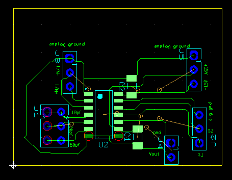
IC. Blue line is the output. The whole circuit is put into a box as shown in last figure above. 4th figure shows the pcb connections for IC IVC102.
As can be seen in 3rd figure the output of IC is not linearly rising but is constant at 2V.
Given below is pcb design for the IC IVC102. Why am I observing such behavior from the IC?


