Part Number: TMDX654IDKEVM
Environment:
Code Composer Studio Version: 9.2.0.00013
pdk_am65xx_1_0_5
Part Number TMDX654IDKEVM AM65x industrial development kit (IDK)
Dear Support Team,
Currently, I am researching the interrupt system (INTC) of PRU and communication to ARM and would like to clarify some questions.
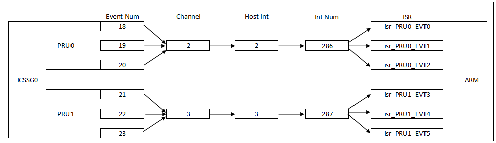
I would like to implement the following functionality:
- PRU0 must notify ARM about the occurrence of the events Event0, Event1 and Event2. On the ARM side, the interrupt service routines isr_pru0_evnt0, isr_pru0_evnt1 and isr_pru0_evnt2 must be invoked respectively.
- PRU1 must notify ARM about the occurrence of the events Event3, Event4 and Event5. On the ARM side, the interrupt service routines isr_pru1_evnt3, isr_pru1_evnt4 and isr_pru1_evnt5 must be invoked respectively.
Following TRM “6.4.7.1 PRU_ICSSG Interrupt Controller Functional Description” as well as “Figure 6-148. PRU_ICSSG Interrupt Controller Block Diagram”, which states that
- Multiple interrupts can be mapped to a single channel;
- Multiple channels can be mapped to a single host interrupt;
I'd like to implement the following interrupt scheme:
For this purpose, I have developed a small test application that initializes the PRU’s INTC using the following PRUICSS_INTC_INITDATA structure:
#define ARM_PRU0_EVENT 16 // pr0_pru_mst_intr[0]_intr_req 32
#define ARM_PRU1_EVENT 17 // pr0_pru_mst_intr[1]_intr_req 33
#define PRU0_ARM_EVENT0 18 // pr0_pru_mst_intr[2]_intr_req 34
#define PRU0_ARM_EVENT1 19 // pr0_pru_mst_intr[3]_intr_req 35
#define PRU0_ARM_EVENT2 20 // pr0_pru_mst_intr[4]_intr_req 36
#define PRU1_ARM_EVENT3 21 // pr0_pru_mst_intr[5]_intr_req 37
#define PRU1_ARM_EVENT4 22 // pr0_pru_mst_intr[6]_intr_req 38
#define PRU1_ARM_EVENT5 23 // pr0_pru_mst_intr[7]_intr_req 39
#define CHANNEL0 0
#define CHANNEL1 1
#define CHANNEL2 2
#define CHANNEL3 3
#define CHANNEL4 4
#define CHANNEL5 5
#define CHANNEL6 6
#define CHANNEL7 7
#define CHANNEL8 8
#define CHANNEL9 9
#define PRU0 0
#define PRU1 1
#define PRU_EVTOUT0 2
#define PRU_EVTOUT1 3
#define PRU_EVTOUT2 4
#define PRU_EVTOUT3 5
#define PRU_EVTOUT4 6
#define PRU_EVTOUT5 7
#define PRU_EVTOUT6 8
#define PRU_EVTOUT7 9
#define PRU0_HOSTEN_MASK 0x0001
#define PRU1_HOSTEN_MASK 0x0002
#define PRU_EVTOUT0_HOSTEN_MASK 0x0004
#define PRU_EVTOUT1_HOSTEN_MASK 0x0008
#define PRU_EVTOUT2_HOSTEN_MASK 0x0010
#define PRU_EVTOUT3_HOSTEN_MASK 0x0020
#define PRU_EVTOUT4_HOSTEN_MASK 0x0040
#define PRU_EVTOUT5_HOSTEN_MASK 0x0080
#define PRU_EVTOUT6_HOSTEN_MASK 0x0100
#define PRU_EVTOUT7_HOSTEN_MASK 0x0200
#define SYS_EVT_POLARITY_LOW 0
#define SYS_EVT_POLARITY_HIGH 1
#define SYS_EVT_TYPE_PULSE 0
#define SYS_EVT_TYPE_EDGE 1
#define PRUICSS_INTC_INITDATA { \
{ \
ARM_PRU0_EVENT, \
ARM_PRU1_EVENT, \
PRU0_ARM_EVENT0, \
PRU0_ARM_EVENT1, \
PRU0_ARM_EVENT2, \
PRU1_ARM_EVENT3, \
PRU1_ARM_EVENT4, \
PRU1_ARM_EVENT5, \
0xFF \
}, \
{ { ARM_PRU0_EVENT, CHANNEL0, SYS_EVT_POLARITY_HIGH, SYS_EVT_TYPE_PULSE },\
{ ARM_PRU1_EVENT, CHANNEL1, SYS_EVT_POLARITY_HIGH, SYS_EVT_TYPE_PULSE },\
{ PRU0_ARM_EVENT0, CHANNEL2, SYS_EVT_POLARITY_HIGH, SYS_EVT_TYPE_PULSE }, \
{ PRU0_ARM_EVENT1, CHANNEL2, SYS_EVT_POLARITY_HIGH, SYS_EVT_TYPE_PULSE }, \
{ PRU0_ARM_EVENT2, CHANNEL2, SYS_EVT_POLARITY_HIGH, SYS_EVT_TYPE_PULSE }, \
{ PRU1_ARM_EVENT3, CHANNEL3, SYS_EVT_POLARITY_HIGH, SYS_EVT_TYPE_PULSE }, \
{ PRU1_ARM_EVENT4, CHANNEL3, SYS_EVT_POLARITY_HIGH, SYS_EVT_TYPE_PULSE }, \
{ PRU1_ARM_EVENT5, CHANNEL3, SYS_EVT_POLARITY_HIGH, SYS_EVT_TYPE_PULSE }, \
{ 0xFF, 0xFF, 0xFF, 0xFF }\
}, \
{ { CHANNEL0, PRU0 }, \
{ CHANNEL1, PRU1 }, \
{ CHANNEL2, PRU_EVTOUT0 },\
{ CHANNEL3, PRU_EVTOUT1 },\
{ 0xFF, 0xFF } \
}, \
(PRU0_HOSTEN_MASK | PRU1_HOSTEN_MASK | PRU_EVTOUT0_HOSTEN_MASK | PRU_EVTOUT1_HOSTEN_MASK)\
}
I register the interrupt handlers as follows:
PRUICSS_registerIrqHandler(pruIcssHandle, PRU_EVTOUT0, 286, 18, 1, isr_pru0_evt0);
PRUICSS_registerIrqHandler(pruIcssHandle, PRU_EVTOUT1, 286, 19, 1, isr_pru0_evt1);
PRUICSS_registerIrqHandler(pruIcssHandle, PRU_EVTOUT2, 286, 20, 1, isr_pru0_evt2);
PRUICSS_registerIrqHandler(pruIcssHandle, PRU_EVTOUT3, 287, 21, 1, isr_pru1_evt3);
PRUICSS_registerIrqHandler(pruIcssHandle, PRU_EVTOUT4, 287, 22, 1, isr_pru1_evt4);
PRUICSS_registerIrqHandler(pruIcssHandle, PRU_EVTOUT5, 287, 23, 1, isr_pru1_evt5);
As a result, the application behaves as follows:
On the PRU side, writing the following values to register R31:
34 (pr0_pru_mst_intr[2]_intr_req ())
35 (pr0_pru_mst_intr[3]_intr_req ())
36 (pr0_pru_mst_intr[4]_intr_req ())
always results in invoking the isr_pru0_evt0. The isr_pru0_evt1 (for event num. 35) and the isr_pru0_evt2 (for event num. 36) are NOT invoked.
Writing the following values to register R31:
37 (pr0_pru_mst_intr[5]_intr_req ())
38 (pr0_pru_mst_intr[6]_intr_req ())
39 (pr0_pru_mst_intr[7]_intr_req ())
always results in invoking the isr_pru1_evt3. The isr_pru1_evt4 (for event num. 38) and the isr_pru1_evt5 (for event num. 39) are NOT invoked.
I'm expecting that when I'm writing a value
34 (pr0_pru_mst_intr[2]_intr_req()) the isr_pru0_evt0() would be invoked;
35 (pr0_pru_mst_intr[3]_intr_req()) the isr_pru0_evt1() would be invoked;
36 (pr0_pru_mst_intr[4]_intr_req()) the isr_pru0_evt2() would be invoked;
37 (pr0_pru_mst_intr[5]_intr_req()) the isr_pru1_evt3() would be invoked;
38 (pr0_pru_mst_intr[6]_intr_req ()) the isr_pru1_evt4() would be invoked;
39 (pr0_pru_mst_intr[7]_intr_req ()) the isr_pru1_evt5() would be invoked;
I suspect that during the registration of the interrupt handlers the parameters
uint32_t pruEvtoutNum,
int32_t eventNum,
are specified wrong.
Although the answer to this question is quite obvious, I could not find a precise description of what values should be passed for these parameters. I have studied similar branches on the forum and tried several different combinations of values (except those mentioned above), but I could not achieve the desired result. Could you please explain how these parameters are evaluated and provide links to the technical documentation that contains this information?
Thank you in advance!